안녕하세요.
이번에는 Fortigate LACP에 대해서 알아보겠습니다.

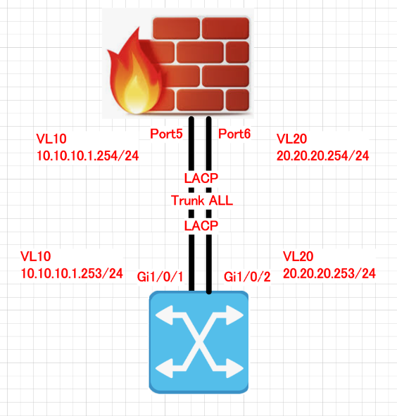
Fortigate 설정 입니다.
1. LACP Interface를 설정합니다.
name: LACP01
Alias: LACP01
Type: 802.3ad aggregate
Interface member: port5 and port6
Role: Lan
IP: none
그리고 Save를 클릭 합니다.

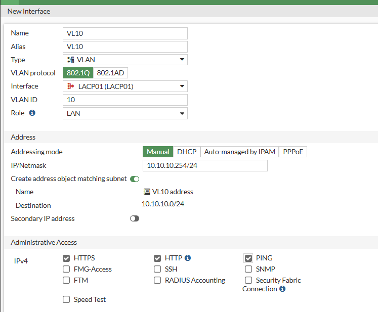
2. VL10 Interface를 설정합니다.
Name: VL10
Alias: VL10
Type: VLAN
Interface LACP01
VLAN ID: 10
Role: LAN
IP: 10.10.10.254/24

2. VL20 Interface를 설정합니다.
Name: VL20
Alias: VL20
Type: VLAN
Interface LACP01
VLAN ID: 20
Role: LAN
IP: 10.10.10.254/24

Interface를 확인 합니다.

SW 설정입니다.
1. LACP 설정
| Switch(config)#int range g1/0/1-2 Switch(config-if-range)#channel-group 1 mode active Creating a port-channel interface Port-channel 1 Switch(config-if-range)#int po 1 Switch(config-if)#sw mode tr Switch(config-if)# |
2. VLAN and SVI 설정
| Switch(config)#vlan 10 Switch(config-vlan)#vlan 20 Switch(config-vlan)#int vlan 10 Switch(config-if)#ip add 10.10.10.253 255.255.255.0 Switch(config-if)#int vlan 20 Switch(config-if)#ip add 20.20.20.253 255.255.255.0 Switch(config-if)#end Switch# |
3. Status 상태 확인
| Switch#show vlan brie VLAN Name Status Ports ---- -------------------------------- --------- ------------------------------- 1 default active Gi1/0/1, Gi1/0/2, Gi1/0/3 Gi1/0/4, Gi1/0/5, Gi1/0/6 Gi1/0/7, Gi1/0/8, Gi1/0/9 Gi1/0/10, Gi1/0/11, Gi1/0/12 Gi1/0/13, Gi1/0/14, Gi1/0/15 Gi1/0/16, Gi1/0/17, Gi1/0/18 Gi1/0/19, Gi1/0/20, Gi1/0/21 Gi1/0/22, Gi1/0/23, Gi1/0/24 Te1/1/1, Te1/1/2, Te1/1/3 Te1/1/4 4 VLAN0004 active 10 VLAN0010 active 20 VLAN0020 active Switch#show ip int brie Interface IP-Address OK? Method Status Protocol Vlan1 unassigned YES NVRAM down down Vlan10 10.10.10.253 YES manual down down Vlan20 20.20.20.253 YES manual down down |
4. 케이블 연결

5. LACP 확인
| Switch#show etherchannel summary Flags: D - down P - bundled in port-channel I - stand-alone s - suspended H - Hot-standby (LACP only) R - Layer3 S - Layer2 U - in use f - failed to allocate aggregator M - not in use, minimum links not met u - unsuitable for bundling w - waiting to be aggregated d - default port A - formed by Auto LAG Number of channel-groups in use: 1 Number of aggregators: 1 Group Port-channel Protocol Ports ------+-------------+-----------+----------------------------------------------- 1 Po1(SU) LACP Gi1/0/1(P) Gi1/0/2(P) Switch# |
6. Ping 테스트
| Switch#ping 10.10.10.254 source vlan 10 Type escape sequence to abort. Sending 5, 100-byte ICMP Echos to 10.10.10.254, timeout is 2 seconds: Packet sent with a source address of 10.10.10.253 .!!!! Success rate is 80 percent (4/5), round-trip min/avg/max = 1/1/4 ms Switch#ping 20.20.20.254 sou Switch#ping 20.20.20.254 source vlan 20 Type escape sequence to abort. Sending 5, 100-byte ICMP Echos to 20.20.20.254, timeout is 2 seconds: Packet sent with a source address of 20.20.20.253 .!!!! Success rate is 80 percent (4/5), round-trip min/avg/max = 1/1/4 ms Switch# |
지금까지 fortigate인터페이스를 LACP설정하고 VLAN10 and VLAN20 interface 만들어서 Cisco Switch랑 통신 하는 방법에 대해서 알아보았습니다.
지금까지 글을 읽어주셔서 감사합니다.
'FORTINET > FORTIGATE 방화벽' 카테고리의 다른 글
| [Fortigate-#14]- firewall does not work after upgrading firmware (0) | 2024.12.11 |
|---|---|
| [Fortigate-#13]- password recovery (1) | 2024.12.11 |
| [Fortigate-#11]- VLAN on Port (0) | 2024.11.27 |
| [Fortigate-#10]- spanning-tree (0) | 2024.11.27 |
| [Fortigate-#9]- VLAN-Switch(Hardware-Switch) (0) | 2024.11.27 |