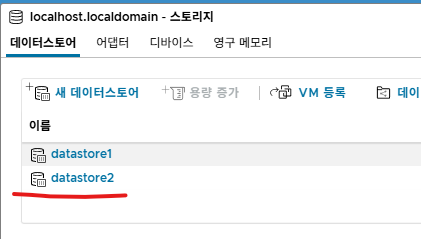
안녕하세요


오늘은 VMware ESXi에 Windows11를 설치하겠습니다.


1. VMware ESXi 접속합니다

제 서버 IP주소는 192.168.10.219 입니다.


2. VM 생성/등록을 클릭 합니다. 


3. 

새 가상 시스템 생성 클릭후 다음버튼을 클릭 합니다. 


4. 아래처럼 선택하고 다음을 클릭합니다. 


5. datastore2를 선택하고 다음버튼을 클릭합니다. 


6. 아래처럼 수정합니다. 


7. 윈도우11 ISO를 선택하고 다음 버튼을 클릭합니다. 


8. 완료버튼을 클릭합니다. 


9. 실행버튼을 클릭합니다. 


10. 설치를 진행 합니다. 


11. 다음버튼을 클릭합니다. 


12. 다음버튼을 클릭합니다. 


13. 다음버튼을 클릭합니다. 


14. 제품 키가 없습니다. 클릭합니다. 


15. Pro를 선택합니다. 


16. 설치를 계속 진행중에 아래처럼 에러 메시지가 발생합니다.


17. 아래 블로그를 참고 부탁드립니다. 

https://itblog-kr.tistory.com/manage/posts/


티스토리

좀 아는 블로거들의 유용한 이야기, 티스토리. 블로그, 포트폴리오, 웹사이트까지 티스토리에서 나를 표현해 보세요.

www.tistory.com


위에 방식이 해결아 안되면 아래 방식 시도 부탁드립니다.

https://itblog-kr.tistory.com/252


[VMware ESXi][#12]- Windows11 설치 - Error Message 해결방법2

안녕하세요. VMware ESXi7에서 윈도우11 설치 할때 아래처럼 에러 메시지가 발생하는 경우 해결하는 방법에 대해서 알아보겠습니다. 더 에러메시지는 TPM때문에 발생합니다. 1. 설치 하는 과정에서

itblog-kr.tistory.com


18. 동의를 클릭합니다.


19. 다음을 클릭 합니다.


20. 설치 버튼을 클릭합니다.


21. 100% 될때까지 기다립니다.


22. 국가를 선택하고 예 버튼을 클릭합니다. 


23. 예 버튼을 클릭합니다.


24. 건너뛰기를 클릭합니다.


25. 설치 할때 인터넷이 필요합니다.

Offline으로 인터넷없이 설치 하는 방법

shift + f10


아래처럼 입력합니다. 


그리고 아래처럼 인터넷에 연결외어 있지 않음을 클릭 합니다. 


26. 이름을 입력하고 다음버튼을 클릭 합니다. 


27. 암호를 입력합니다.


28. 암호를 다시 입력합니다.


29. 다음버튼을 클릭합니다.


30. 설치가 완료 될때까지 기다립니다.


31. 설치가 완료 되어서 자동으로 부팅 되었습니다.


32. 윈도우11에 VMware Tools 설치를 클릭합니다. 


33. VMware Tools를 클릭 합니다. 


34. setup를 클릭합니다.


35. 예를 클릭합니다.


36. 다음을 클릭합니다.


37. 다음을 클릭합니다.


38. 설치를 클릭합니다.


39. 마침을 클릭합니다.

안녕하세요.


오늘은 VMware ESXi에 Windows10를 설치해보겠습니다.


1. VMware ESXi에 접속 합니다.


2. 다음버튼을 클릭 합니다. 


3. 아래처럼 입력 합니다. 


4. Disk를 선택합니다. 


5. 아래처럼 입력 합니다. 

CD/DVD드라이브 클릭해서 WIN10 ISO파일을 선택합니다. 


6. 완료버튼을 클릭 합니다. 


7. VM 실행합니다. 


8. Windows10 설치합니다. 


9. 다음을 클릭합니다. 


10. 설치를 진행합니다. 


11. 제품 키 없음 선택하고 다음을 클릭 합니다. 


12. Pro를 선택하고 다음버튼을 클릭 합니다. 


13. 다음버튼을 클릭 합니다. 


14. Windows만 설치(고급) 선택합니다. 


15. 다음을 클릭 합니다. 


16. 설치가 완료 될때까지 기다립니다. 


17. 나라를 선택합니다.

한국


18. 다음버튼을 클릭 합니다. 


19. 건너뛰기 클릭 합니다. 


20. 인터넷 없음 클릭 합니다. 


21. 제한된 설치로 계속 선택


22. 다음버튼을 클릭 합니다. 


23. 암호를 입력합니다.


24. 암호를 재입력합니다. 


25. 수락버튼을 클릭합니다. 


26. 완료 될때까지 기다립니다. 


27. 설치가 완료되고 부팅이 완료 되었습니다. 


28. 

VMware Tools 설치합니다. 아래 버튼을 클릭 합니다.. 


29. 클릭해서 설치 합니다. 


30. 다음을 클릭합니다. 


31. 다음을 클릭합니다. 


32. 설치를 클릭합니다. 


33. 마침을 클릭합니다. 


34. 예 버튼을 클릭해서 재부팅 됩니다. 

그리고 VMware Tools이 적용 됩니다. 


지금까지 [VMware ESXi][#7]- Windows10 설치 글을 읽어주셔서 감사합니다. 

안녕하세요.


이번에는 PNETlab Disk를 확장해보겠습니다.


0. 공식 홈페이지 입니다. 참고 부탁드립니다.

https://pnetlab.com/pages/documentation?slug=how-to-expand-hdd-for-pnetlab


PNETLab : Lab is Simple


pnetlab.com


1. 제 PNETlab 서버 IP주소는 192.168.10.219입니다.

2. SSH 접속해서 df -h 입력합니다.

root@pnetlab:~# df -h
Filesystem                         Size  Used Avail Use% Mounted on
udev                                63G     0   63G   0% /dev
tmpfs                               13G   14M   13G   1% /run
/dev/mapper/ubuntu--vg-ubuntu--lv   97G  8.2G   84G   9% /
tmpfs                               63G     0   63G   0% /dev/shm
tmpfs                              5.0M     0  5.0M   0% /run/lock
tmpfs                               63G     0   63G   0% /sys/fs/cgroup
/dev/sda2                          976M  156M  754M  18% /boot
tmpfs                               13G     0   13G   0% /run/user/0
root@pnetlab:~# ^C
root@pnetlab:~#


3. PNETlab VM을 종료 합니다. 

root@pnetlab:~# init 0


4. 설정 편집을 클릭 합니다. 


5. 하드 디스크를 추가 합니다.

설치 할때 1T 설정 하였는데, 기본 하드 디스크1은 디폴트로 100G로 fix되어져 있어서 디스크 사이즈를 수정해도 실제 PNETlab안에 disk size가 수정되지 않습니다.


6. 새 하드디스크를 추가하고 900G를 입력합니다.

그리고 디스크 프로비저닝은 씬 프로비저닝을 선택하고 저장 버튼을 클릭 합니다. 


7. VM를 실행 합니다.

8. 아래 IP로 접속합니다. 


9. 약 1T로 수정 되었습니다. 


10. CLI에서 확인 하기


아래 983G 표시 되었습니다. 

root@pnetlab:~# df -h
Filesystem                         Size  Used Avail Use% Mounted on
udev                                63G     0   63G   0% /dev
tmpfs                               13G   14M   13G   1% /run
/dev/mapper/ubuntu--vg-ubuntu--lv  983G  8.2G  934G   1% /
tmpfs                               63G     0   63G   0% /dev/shm
tmpfs                              5.0M     0  5.0M   0% /run/lock
tmpfs                               63G     0   63G   0% /sys/fs/cgroup
/dev/sda2                          976M  156M  754M  18% /boot
tmpfs                               13G     0   13G   0% /run/user/0


지금까지 [VMware ESXi][#6]- PNETlab Disk 확장 글을 읽어주셔서 감사합니다.


안녕하세요.


이번에는 VMware ESXi에서 PNETlab를 설치 해보겠습니다.

HOME-LAB ESXi 서버 조립은 아래를 참고 부탁드립니다.

https://itblog-kr.tistory.com/244


[VMware ESXi][#3]- ESXi USB 만들기

안녕하세요. 이번에 테스트를 위해서 VMware ESXi Home-LAB 서버를 조립하였습니다. 이번에는 서버에 VMware ESXi를 설치하기 위해서 부팅용 USB를 만들어 보겠습니다. 1. 아래처럼 준비물을 준비 합니다.

itblog-kr.tistory.com


1. PNETlab 공식 홈페이지에서 파일을 다운로드 받습니다. 

https://www.pnetlab.com/pages/main


PNETLab : Lab is Simple

Total Users 91878 Total Labs 1309 Labs Downloaded 588658  Our Partners and Customers

www.pnetlab.com


2. Download 버튼을 클릭 합니다.


3. 아래 링크를 클릭 합니다. 


4. 다운로드 버튼을 클릭 합니다. 


5. VMware ESXi에 접속 합니다. 

https://192.168.10.220


VM생성/등록 버튼을 클릭 합니다. 


6. OVF 또는 OVA파일에서 가상 시스템 배포 선택하고  다음 버튼을 클릭 합니다. 


7.

가상 시스템의 이름: PNETLAB01 

그리고 PNETlab 파일을 드래그 합니다

다음 버튼을 클릭 합니다. 


8. datastore1를 클릭하고 다음 버튼을 클릭 합니다. 


9. 

디스크: 씬

자동으로 전원켜기 - 체크를 해지 합니다. 


10. 완료 버튼을 클릭 합니다. 


11. 배포가 진행됩니다. 완료 될때까지 기다립니다.


12. 설정 편집을 클릭 합니다. 


13. CPU는 아래처럼 설정 합니다. 


14. 

메모리 128G

하디 디스크 1TB를 설정합니다. 

그리고 저장 버튼을 클릭 합니다. 


15, PNETLAB01를 실행 합니다. 


16. 설치가 진행 됩니다. 완료 될때까지 기다립니다. 


17. 설치가 완료되면 아래처럼 로그인 합니다.

root/pnet


18. 패스워드를 설정 합니다.


19. 패스워드를 한번더 입력 합니다. 


20. 디폴트값을 사용 합니다. OK버튼을 클릭 합니다. 


21. Static를 선택하고 OK버튼을 클릭 합니다. 


22. IP주소를 입력 합니다. 


23. 네트워크 마스크를 입력합니다.


24. 디폴트케이트웨이를 입력합니다. 


25. DNS를 입력 합니다. 


26. 2번째 DNS를 입력 합니다.


27. 기본값 사용 그냥 OK버튼을 클릭 합니다. 


28. 기본값 Direct Connection를 선택하고 OK버튼을 클릭 합니다. 


29. VM이 자동으로 재부팅 되고, 아래처럼 IP주소가 표시 됩니다.


30. PC에서 PING를 합니다.

192.168.10.219


31. PNETlab에 접속 합니다.

192.168.10.219


Offline Mode를 선택합니다. 


32. admin/pnet

login버튼을 클릭 합니다. 


33. SYSTEM를 클릭 합니다. 


34. 

CPU: 16 Cores

MEM: 128G

Disk: 100G 

저희가 1T 설정 하였는데, 100G로만 인식 됩니다.


하디 디스크 용량 확장하는 방법은 나중에 확인하고 블로그 올리겠습니다. 


지금까지 [VMware ESXi][#5]- PNETlab 설치 글을 읽어주셔서 감사합니다. 

안녕하세요. 


이번에 테스트를 위해서 VMware ESXi Home-LAB 서버를 조립하였습니다. 

이번에는 서버에 VMware ESXi를 설치하기 위해서 부팅용 USB를 만들어 보겠습니다.


1. 아래처럼 준비물을 준비 합니다.

    1-1 USB

    1-2 Rufus 프로그램

    1-3 VMware ESXi 7 다운로드 받습니다. 


2. Rufus 프로그램 설치 합니다. 

  https://rufus.ie/ko/


Rufus - 간편한 방법으로 부팅 가능한 USB 드라이브 만들기

Rufus는 USB 키/펜드라이브, 메모리 스틱 등과 같은 부팅 가능한 USB 플래시 드라이브를 포맷하고 생성하는 데 도움이 되는 유틸리티입니다. Rufus는 작은 크기에도 불구하고 필요한 모든 것을 제공

rufus.ie


3. VMware ESXi를 다운로드 받습니다. 

회원가입후 Trial License 다운로드 가능 합니다. 

https://access.broadcom.com/default/ui/v1/signin/


https://access.broadcom.com/default/ui/v1/signin/

{PRELOAD_FONT} {PRELOAD_FONT} {PRELOAD_FONT} {PRELOAD_FONT}

access.broadcom.com


4. USB를 노트북에 연결 합니다. 그리고 Rufus 프로그램을 실행 합니다. 

USB가 정상적으로 인식 되었으면 아래처럼 USB가 표시 됩니다.


5. 시작버튼을 클릭 합니다. 그리고 확인 버튼을 클릭 합니다. 


6. 완료 될때까지 기다립니다. 


완료 되면 아래처럼 닫기 버튼을 클릭 합니다. 


지금까지 [VMware ESXi][#3]- ESXi USB 만들기 글을 읽어주셔서 감사합니다. 

안녕하세요.


EVE-NG 또는 PNETLAB 설치 하기 위해서 HOME-LAB ESXi 서버를 조립 했습니다. 


다나와 가격 기준 입니다. 


CPU: AMD 9700X 48만원

쿨러: 기본 쿨러

메인보드: 기가바이트 B650M K 제이씨현 14만원

RAM:  96G 마이크론 Crucial DDR5-5600 CL46 PRO 37만원 

            96G 마이크론 Crucial DDR5-5600 CL46 PRO 37만원 

           총 램 192G 74만원

M2 NVME PCIE4 -  Seagate 파이어쿠다 530R M.2 NVMe 2T 23만원

                                 Seagate 파이어쿠다 530R M.2 NVMe 2T 23만원

                                총 4T 46만원

서버용 4port 1G - 중고로 3만원

잘만 DecaMax 500W 80PLUS스탠다드  - 4만원

M-ATX 케이스 - 마이크로닉스 WIZMAX 오로라 - 2만3천원


총 약 200만원. 

실제 제품을 구매 할때는 다나와 가격보다 조금더 비쌉니다. 그리고 직접 조립해서 조립비는 절약하였습니다. 


지금까지 [VMware ESXi][#2]- HOME-LAB ESXi 서버 조립 글을 읽어주셔서 감사합니다. 

안녕하세요.


오늘은 마이크로소프트에서 윈도우11를 ISO 다운로드를 받아보겠습니다.


1. 꼭 익터넷익스플로러를 실행합니다. 

Windows 11 다운로드


Windows 11 다운로드

이 옵션은 부팅 가능한 설치 미디어(USB 플래시 드라이브, DVD)를 만들거나 가상 컴퓨터(.ISO 파일)을 만들어 Windows 11을 설치하려는 사용자를 위한 옵션입니다. 이 다운로드는 제품 키를 통해 올바

www.microsoft.com


2. 아래처럼 클릭 합니다. 


3. 아래처럼 클릭 합니다.


4. Use Browser Default를 uncheck하고 아래처럼 blackberry -BB10를 선택 합니다. 


5. 새로고침을 합니다. F5 그리고 아래처럼 windows 11선택하고 지금 다운로드를 선택합니다. 


6. 한국어를 선택하고 확인을 선택합니다. 


7. 64bit를 선택 합니다.

8. 아래처럼 다운로드가 시작 됩니다.


지금까지 Windows 11 ISO 다운로드 받기 글을 읽어주셔서 감사합니다. 

안녕하세요. 


윈도우10은 마이크로소프트로부터 2025년 10월 14일부터 공식적으로 업데이트를 제공 하지 않습니다.


https://www.microsoft.com/en-sg/windows/end-of-support?r=1


End of support for Windows 10, Windows 8.1 and Windows 7 | Microsoft Windows

Make a smooth transition to Windows 11 from your unsupported operating system with help from Microsoft. Enjoy the benefits of upgrading to a Windows 11 PC.

www.microsoft.com


이번에는 마이크로포스트에서 윈도우 10 ISO파일을 다운로드 받아보겠습니다.


1. 인터넷 익스프로러 실행 합니다 하고 아래 파일을 클릭 합니다. 

Download Windows 10


Download Windows 10

To get started, you will first need to have a license to install Windows 10. You can then download and run the media creation tool. For more information on how to use the tool, see the instructions below.

www.microsoft.com


2. 아래 처럼 링크를 클릭 합니다. 


3. 아래처럼 클릭 합니다. 


4. 아래 use browser default를 uncheck하고 아래처럼 BlackBerry --BB10 선택 합니다. 


5. 새로고침을 합니다. F5

아래처럼 Windows 10 Multi-edition ISO 선택하고 Confirm를 누르면 ISO 다운로드 됩니다. 


6. 아래 Korean를 언어를 선택하고 Confirm버튼을 클릭 합니다. 


7. 아래 64bit를 선택 합니다.  


8. 아래처럼 다운로드가 가능 합니다. 


아래 처럼 90일 간은 trial period로 사용 가능 합니다.


The only official trial of Windows 10 is the 90 day Enterprise trial. Editions such as Pro, Home or Education that you can download and install without activating are actually in a reduced functional mode


지금까지 Windows 10 ISO 다운로드 받기 글을 읽어주셔서 감사합니다.

안녕하세요.


오늘은 2.4GHz 채널에 대해서 알아보겠습니다.


2.4GHZ는 20MHz Wide로 14채널을 가지고 있습니다. 여기에서 채널 간섭이 없는 채널은 1.6.11 입니다.


AP 12설치하고 2.4GHz 사용한다고 가정하면 아래처럼 시그럴 파워랑 위치를 잘 선정해야 합니다.

아니면 채널 간섭때문에 속도가 제대로 나오지 않습니다. 


WIFI버전별 속도

WI-FI 1 802.11b 1~11Mbps 1999 2.4Ghz    
WI-FI 2 802.11a 1.5~54Mbps 1999 5Ghz    
WI-FI 3 802.11g 3~54Mbps 2003 2.4Ghz    
WI-FI 4 802.11n 72~600Mbps 2009 2.4/5Ghz 다중 안테나 기술과 채널 본딩 지원
WI-FI 5 802.11ac 433~6933Mbps 2014 5Ghz 1G 무선랜 지원
WI-FI 6 802.11ax 600~9608Mbps 2019 2.4/5Ghz
1-6Ghz ISM
10G 무선랜 지원


PC나 단말기 Wireless 단말기는 2T2R이다. T -> 전송 R -> 받음. 
노트북 무선랜이 최고 속도를 내기위해서는  8x8를 지원해야한다. 아래 그림을 참조 부탁드립니다. 

안녕하세요.


현재 노트북에서 WPA3를 지원하는 무선랜카드가 있어야지 WPA3를 사용 할수 있습니다.

지원하지 않으면 SSID - WPA3 사용하는 SSID는 접속 할수 없습니다.


1. cmd 


C:\Users\USER>netsh wlan show wirelesscapabilities

무선 시스템 기능
----------------------------
    802.11 라디오에 연결된 안테나 수(값을 사용할 수 없음)
    장치가 동시에 작동할 수 있는 채널의 최대 수(값을 사용할 수 없음)
    동시 존재 지원                        : 알 수 없음


무선 장치 기능
----------------------------

인터페이스 이름: Wi-Fi

    WDI 버전(Windows)                       : 0.1.1.12
    WDI 버전(IHV)                           : 0.1.1.12
    WiFiCx 버전 (IHV)                        : WiFiCx 인터페이스 지원되지 않음
    펌웨어 버전                            : rtwlane
    스테이션                                     : 지원됨
    소프트 AP                                     : 지원되지 않음
    네트워크 모니터 모드                        : 지원되지 않음
    Wi-Fi Direct 장치                         : 지원됨
    Wi-Fi Direct GO                             : 지원됨
    Wi-Fi Direct 클라이언트                         : 지원됨
    보호 관리 프레임                 : 지원됨
    DOT11k 인접 라우터 보고서                      : 지원됨
    ANQP 서비스 정보 검색          : 지원됨
    작업 프레임                                : 지원됨
    다양성 안테나                           : 지원하지 않음
    IBSS                                        : 지원하지 않음
    무차별 모드                             : 지원하지 않음
    P2P 장치 검색                        : 지원됨
    P2P 서비스 이름 검색                  : 지원하지 않음
    P2P 서비스 정보 검색                  : 지원하지 않음
    P2P 백그라운드 검색                    : 지원하지 않음
    5GHz의 P2P GO                             : 지원됨
    ASP 2.0 서비스 이름 검색              : 지원하지 않음
    ASP 2.0 서비스 정보 검색       : 지원하지 않음
    IP 도킹 지원                          : 지원하지 않음
    FIPS                                        : 지원됨
    인스턴트 연결                             : 지원됨
    Dx 대기 모드 NLO                              : 지원됨
    확장 채널 전환 알림        : 지원됨
    기능 수준 초기화                        : 지원됨
    플랫폼 수준 초기화                        : 지원됨
    버스 수준 초기화                             : 지원됨
    MAC 임의 지정                           : 지원됨
    빠른 전환                             : 지원됨
    MU-MIMO                                     : 지원됨
    Miracast 싱크                               : 지원됨
    BSS 전환 (802.11v): 지원됨
    IHV 확장성 모듈이 구성됨         : 지원하지 않음
    SAE 인증: 지원됨
    SAE 해시-요소 인증          : 지원됨
    WPA3 SUITE B 인증                 : 지원됨
    WPA3 SUITE B FIPS 모드                      : 지원하지 않음
    OWE 인증                          : 지원됨
    개시 장치 FTM                            : 지원하지 않음
    MBO 지원                                 : 지원됨
    Tx 공간 스트림 수                : 2
    Rx 공간 스트림 수                : 2
    지원되는 동시 채널 수     : 2
    P2P GO 포트 수                          : 1
    P2P 클라이언트 포트 수                      : 1
    P2P 최대 모바일 AP 클라이언트 수                   : 8
    지원되는 최대 ANQP 서비스 보급 알림 수   : 0
    지원되는 최대 보조 STA 수 : 0
    지원되는 다중링크 연결 수   : 0
    동시 존재 지원                        : Wi-Fi 성능이 유지됨


C:\Users\USER>


지금까지 무선 랜카드 WPA3 지원 확인 방법 글을 읽어주셔서 감사합니다. 

안녕하세요.


이번에는 WIFI 분석 관련 툴을 확인해보겠습니다.


일반 노트북에서 SSID 암호화 방식 WPA1,2,3 또는 WIFI Signal 확인 등이 가능 합니다.


https://www.netspotapp.com/


NetSpot WiFi Site Survey Software: WiFi Heat Maps, Network Planning Tool. Free Plan.

NetSpot helps you plan wireless networks, create WiFi heat maps, run wireless site surveys & analyze Wi-Fi on Mac OS, Windows and Android, free versions available.

www.netspotapp.com


1. 아래 Download Free Version를 클릭 합니다. 


2. 자동으로 다운로드 되면서 아래 페이지로 리다이렉트 됩니다.


3. 다운로드 받은 파일을 실행 합니다.

4. OK버튼을 클릭 합니다. 

5. 설치 합니다. 

6. 아래 Start 버튼을 클릭 합니다. 


7. 무료 버전에서는 아래 처럼

    1. WI-FI Site Surveys

    2. Future WI-FI Planning
    3. 20+ types of WI-FI heatmaps

    4. Active Scanning


라이센스 가격


무료버전에서 사용 할수 있는 기능들입니다.


아래처럼 클릭하면 2.4G 5G 6G 관련 그래프등으로도 확인 가능 합니다. 

Kevin-5G 클릭 하면 아래 정보를 확인 가능 합니다. 


Survey - 무료 버전에서는 사용 할수 없고, Sample 파일에 클릭해서 어떤 용도로 사용 가능 한지 확인 가능 합니다. 


Planning 무료 버전에서는 Create New를 사용 할수 없고 Sample에서 어떻게 사용 하는지 참고 가능 합니다. 

AP 이동해서 AP Singal coverage를 확인 가능 합니다. 


지금까지 Netspot - WIFI 검색/분석/계획/문제해결 가능한 프로그램  글을 읽어주셔서 감사합니다. 

'IT TECH TIP' 카테고리의 다른 글

Windows 10 ISO 다운로드 받기  (0) 2025.05.17
무선 랜카드 WPA3 지원 확인 방법  (0) 2025.04.24
Fortinet 파트너 등록 정보  (0) 2025.04.18
[C9300] - 장비 공부  (0) 2025.04.18
[C4506-E] - 장비 공부  (2) 2025.04.18

Engage-Partner-Program-Brochure-9-1-24 (2).pdf
1.05MB


자세한 내용은 첩부 파일 참고 부탁드립니다. 

안녕하세요.


Fortinet의 Hardware, Software 제품에 대한  EOO, EOES, EOS, EOL 등에 대한 정책 문서이다.


Cycle Policy http://www.fortinet.com
Product Life Cycle Policy
To ensure we provide innovative solutions, Fortinet products are periodically discontinued. This life cycle policy
provides customers with the required information to ensure a seamless migration to next-generation Fortinet
solutions. A product is defined as;
• All hardware products and the associated appliance services such as FortiCare and FortiGuard
• Software, which is any and all software produced and/or sold by Fortinet, such as hardware operating
systems firmware, for example FortiOS, as well as applications installed on customer owned systems for
example FortiClient.
• Appliance services, including FortiGuard branded subscription services, provided by Fortinet and which can
be run on authorized devices and/or software clients
• All other services, referred to as ‘’Stand-alone’’ services which are linked to a specific set of deliverables, an
example would be Premium Technical Support.
End-of-Life Notifications
As a product approaches the end of its active selling phase, Fortinet will publicly communicate the End-of-Life
(‘EOL’). This will be in the form of a notification and will in general indicate how and when the product is to be
withdrawn from sale and support. EOL notifications may also contain other information such as the
recommended replacement product(s).
End of life information is posted to the support web site located at ;
https://support.fortinet.com/Information/ProductLifeCycle.aspx


Lifecycle Milestones
The lifecycle events covered in this policy generally follow the milestones outlined below:
1. General Availability Date (GA): The date at which a product is made generally available to the public and
service contracts are available for purchase.


2. End of Life Notification (EOLN): An EOLN contains information regarding the end of support and the last
order date. For firmware, the EOL date is normally available on the GA date.


3. End of Order Date (EOO): The EOO date is the last date on which a product may be ordered. After this
date the product is no longer available for sale. Fortinet will provide a minimum of ninety days advance
notice of the relevant EOO date by publishing an EOL notification. For standalone services the EOO is
the Last Extension Date.


4. Last Service Extension Date (LSED): The last date at which a service extension will be accepted for an
existing contract, for a hardware or software product, that is no longer available for purchase. For
software and hardware products a) no service contracts may be extended past the EOS date and b)
the last service extension date is 12 months before the EOS date for the relevant product. For a standalone
service the last service extension date is 90 days after the end of life notification.


5. End of Engineering Support for Software (EOES): The date beyond which Fortinet no longer commits to
provide engineering support for software. After this date the software enters a must-fix support phase,
during which, maintenance builds will only be produced for industry wide critical issues and PSIRT
vulnerabilities. The EOES date is generally 36 months after the GA date.


6. Final Firmware Release (FFR): The last release of firmware operationally supported on a specific
hardware product. The FFR remains in a must-fix support phase until the EOS date of the applicable
hardware product.


7. End of Support Date (EOS): The final milestone in the lifecycle is the End of Support date. After this date
Fortinet, will not sell, manufacture or improve the product and is under no obligation to provide support
services. In general the EOS takes place as follows:
• Hardware - 60 months after the EOO Date
• Software - 54 months after the GA date
• Stand Alone Services – on the service contract termination date


자세한 내용은 Fortigate 공식 홈페이지에 참고 부탁드립니다. 

'FORTINET > FortiManager' 카테고리의 다른 글

[FortiManager-#6] - RMA - FortiCare  (0) 2025.04.18
[FortiManager-#5] - Trial License  (0) 2025.04.18
[FortiManager-#4] - MGMT 설정  (0) 2025.04.18
[FortiManager-#3] - Ordering Information  (0) 2025.04.18
[FortiManager-#2] - Platforms  (0) 2025.04.18

안녕하세요.


오늘은 FortiCare에 대해서 알아보겠습니다.


FortiCare Essential is the base-level service targeted toward devices that require a limited amount of support and can tolerate next-business-day, web-only response for critical as well as non-critical issues. This service is only offered to FortiGate models 9x and below and to low-end FortiWifi devices. RMA is on a return-and-replace basis at this service level


FortiCare Premium is targeted toward devices that require 24x7x365 with one-hour response for critical issues and the next-business-day response for non-critical issues. Standard next-business-day RMA services are included at this service level. Fortinet will ship a replacement device (Advanced Replacement) the next business day, before we receive the faulty device from the customer. 


FortiCare Elite offers enhanced service-level agreements (SLAs) and accelerated issue resolution. Single-touch ticket handling by the expert technical team streamlines resolution. FortiCare Elite services are available for FortiGate, FortiGate VM, FortiWiFi, FortiManager, FortiAnalyzer, FortiAP, and FortiSwitch appliances. This option also provides access to an intuitive portal with a single unified view of device and security health. Standard next-business-day RMA services are included at this service level. Fortinet will ship a replacement device (Advanced Replacement) the next business day, before we receive the faulty device from the customer


Feature Highlights: Priority RMA Services Standard next-business-day RMA services are included with both Premium and Elite per-device support contracts. Priority RMA (PRMA) add-on options are available across the product family for expedited replacement of defective hardware. Priority RMA options cover weekends and holidays. Only return-and-replace RMA is included with Essential per-device support contract. Essential customers are not eligible for Priority RMA add-on options


Priority RMA Options


1. Next Calendar Day delivery. If the exchange is confirmed, a replacement part will be delivered by courier service and arrive the next calendar day in accordance with the applicable country cutoff time.

2. Four-hour courier. A replacement part will be delivered on-site by a courier service. 

3. Four-hour courier with on-site engineer. A replacement part will be delivered on-site by a courier service. An engineer will arrive separately, rack and cable the appliance, and leave with the defective part if requested.


추가적인 자료는 Fortigate 공식 홈페이지에사 참고 부탁드립니다.

https://www.fortinet.com/content/dam/fortinet/assets/solution-guides/sb-forticare-technical-support-and-rma-services.pdf


안녕하세요.


FortiManager Trial License 신청 방법에 대해서 알아보겠습니다.


FortiManager를 무료 라이센스(기간) 를 사용후 정식 라이센스 구매 가능 합니다. 


Trial License는 아래처럼 제약사항이 있습니다.

1. 2개 ADOM 사용

2. FortiGuard 업데이트 불가

3. 3대 디바이스/VDOM FortiManager 등록 가능

4. Fortinet 서비스 또는 기술 지원 불가


1. 먼저 FortiManager를 설치 합니다.

2. FortiCloud 계정을 생성 합니다.

3. FortiManager에 MGMT IP주소를 설정하고 GUI접속 합니다.

처음 접속시 아래처럼 라이센스 부분 메시지 확인 가능 합니다.


FortiCloud 계정 정보를 입력하고 Free Tiral를 선택하고 Login시도 합니다.

** 인터넷이 사용 가능 해야 로그인 가능 합니다. **


4. 라이센스 동의 관린 글을 읽고 동의하기를 클릭 합니다.


5. 정상적으로 등록이 완료 되면 장비가 재부팅 됩니다.


6. 재부팅후 Trial License가 제대로 FortiCloud Account에 등록 된것을 확인 가능 합니다. 


지금까지 [FortiManager-#5] - Trial License 글을 읽어주셔서 감사합니다. 

안녕하세요.


오늘은 FortiManager GUI접속하기 위해서 MGMT 설정을 합니다.


MGMT PORT1 으로 간주 하겠습니다.


1. IP주소 설정

FortiManager # config system interface
(interface)# edit port1

(port1)# set ip 192.168.10.X/24
(port1)# set allowaccess https

(port1)# end


2. 디폴트게이트웨이 설정

FortiManager # config system route
(route) eidt 1
(1)# set device port1
(1)# set gateway 192.168.10.X


3. https://192.168.10.X 테스트를 합니다.


아래처럼 접속 가능 합니다.

'FORTINET > FortiManager' 카테고리의 다른 글

[FortiManager-#6] - RMA - FortiCare  (0) 2025.04.18
[FortiManager-#5] - Trial License  (0) 2025.04.18
[FortiManager-#3] - Ordering Information  (0) 2025.04.18
[FortiManager-#2] - Platforms  (0) 2025.04.18
[FortiManager-#1] - 기능  (0) 2025.04.18

안녕하세요.


오늘은 FortiManager Ordering Information에 대해서 알아보겠습니다.


자세한 내용은 Fortigate 공식 홈페이지 참고 부탁드립니다.

https://www.fortinet.com/content/dam/fortinet/assets/data-sheets/fortimanager.pdf


'FORTINET > FortiManager' 카테고리의 다른 글

[FortiManager-#6] - RMA - FortiCare  (0) 2025.04.18
[FortiManager-#5] - Trial License  (0) 2025.04.18
[FortiManager-#4] - MGMT 설정  (0) 2025.04.18
[FortiManager-#2] - Platforms  (0) 2025.04.18
[FortiManager-#1] - 기능  (0) 2025.04.18

안녕하세요.


FotiManager를 설치 하기 위한 Platforms에 대해서 알아보겠습니다.


1. Physical - Appliance 

2. Virtual - VM

3. Cloud - PaaS


VM & CLOUD


상세 내용은 fortigate 공식 홈페이지 참고 부탁드립니다. 

https://www.fortinet.com/products/management/fortimanager


Top Network Management Software System & Operation Tool | FortiManager

Fortinet's Network Management Software System offers a security strategy to provide protection against breaches. See how FortiManager Network Management Tool can help automate the workflow.

www.fortinet.com


FortiManager Datasheet

https://www.fortinet.com/content/dam/fortinet/assets/data-sheets/fortimanager.pdf


'FORTINET > FortiManager' 카테고리의 다른 글

[FortiManager-#6] - RMA - FortiCare  (0) 2025.04.18
[FortiManager-#5] - Trial License  (0) 2025.04.18
[FortiManager-#4] - MGMT 설정  (0) 2025.04.18
[FortiManager-#3] - Ordering Information  (0) 2025.04.18
[FortiManager-#1] - 기능  (0) 2025.04.18

안녕하세요.


오늘은 FortiManager에 대해서 알아보겠습니다.


1.  FortiManager는 Fortigate Firewall를 관리 가능 합니다. 

하지만 FortiManager는 단순히 Fortigate Firewall말고 다른 제품군도 관리 가능 합니다.


공식 홈페이지를 참고 합니다.

https://docs.fortinet.com/document/fortimanager/7.6.0/release-notes/907455/supported-models


Supported models | Release Notes


docs.fortinet.com


Supported models

The following tables list which FortiGate, FortiCarrier, FortiDDoS, FortiAnalyzer, FortiMail, FortiSandbox, FortiSwitch ATCA, FortiWeb, FortiCache, FortiProxy, and FortiAuthenticator models and firmware versions that can be managed by a FortiManager or send logs to a FortiManager running version 7.6.0.


This section contains the following topics:

각 링크를 클릭하면 실제 지원 장비 모델을 확인 가능합니다. Fortigate Model를 클릭 합니다.


7.6 버전에서 지원되는 방화벽 장비 리스트가 나옵니다.


https://docs.fortinet.com/document/fortimanager/7.6.0/release-notes/191178/fortigate-models


FortiGate models | Release Notes


docs.fortinet.com


2. Centralized Management

Fortigate장비를 등록해서 장비를 설정 하거나, 방화벽 Firmware Upgrade 가능합니다.


3. Administrative Domains (ADOMs)

ADOMs를 설정해서 장비들을 ADOM별로 등록해서 관리 가능 합니다. 


4. Logging and Reporting

Fortigate Analysis제품이 아느지만, Logging 과 Reporting기능을 제공 합니다.

방화벽 로그들을 Fortimanager 접속해서 방화벽 로그도 확인 가능 합니다.


5. Visibility 

각 장비들에 CPU/MEM 등을 확인 함으로서 FortiManager에 등록된 장비들의 상태 Visibilty 확보가 가능 합니다. 


자세한 내용은 공식 포티케이트 홈페이지에서 참고 부탁드립니다.


https://docs.fortinet.com/document/fortimanager/7.6.2/administration-guide/466992/fortimanager-key-concepts


FortiManager Key Concepts | Administration Guide


docs.fortinet.com


'FORTINET > FortiManager' 카테고리의 다른 글

[FortiManager-#6] - RMA - FortiCare  (0) 2025.04.18
[FortiManager-#5] - Trial License  (0) 2025.04.18
[FortiManager-#4] - MGMT 설정  (0) 2025.04.18
[FortiManager-#3] - Ordering Information  (0) 2025.04.18
[FortiManager-#2] - Platforms  (0) 2025.04.18

안녕하세요.


오늘은 시스코 C9300 장비에 대해서 알아보겠습니다. 


https://www.cisco.com/c/en/us/products/collateral/switches/catalyst-9300-series-switches/nb-06-cat9300-ser-data-sheet-cte-en.html


Catalyst 9300 Series Switches Data Sheet

This data sheet provides detailed information about the Catalyst 9300 series switches, the lead stackable enterprise switching platform for fixed access switches.

www.cisco.com


Table 1.           Product Family Configurations

Models Modular Uplinks and Speeds Stacking Bandwidth Support mGig Density Cisco StackPower HW-Based IPsec App hosting Capacity
Catalyst 9300X 10G, 25G, 40G, mGig and 100G Stackwise-1T (480G when stacking with Catalyst 9300 model) 48x 10G  (Larger Power Budget) Up to 100G IPsec*  (2x hosting resources over Catalyst 9300 models)
Catalyst 9300 10G, 25G, 40G and mGig Stackwise-480 48x5G and 24x10G
Catalyst 9300L Stackwise-320 12x10G
Catalyst 9300LM Stackwise-320 8x10G

C9300장비는 1U 장비 입니다. 


C9300-24T 24 port Data Modular Uplinks 350W AC
C9300-48T 48 port Data Modular Uplinks 350W AC
C9300-24P 24 port PoE+ Modular Uplinks 715W AC
C9300-48P2 48 port PoE+ ENERGY STAR® certified Modular Uplinks 715W AC
C9300-24U 24 port Cisco UPOE Modular Uplinks 1100W AC
C9300-48U 48 port Cisco UPOE Modular Uplinks 1100W AC
C9300-24UX 24 port Multigigabit Cisco UPOE
(10G/5G/2.5G/1G/100M)
Modular Uplinks 1100W AC
C9300-48UXM2 48 port Cisco UPOE, 36 ports 100M/1G/2.5G + 12 ports Multigigabit (10G/5G/2.5G/1G/100M) ENERGY STAR® certified Modular Uplinks 1100W AC
C9300-48UN 48 port 5Gbps Multigigabit UPOE ports (5G/2.5G/1G/100M) Modular Uplinks 1100W AC
C9300-24UB 24 port Cisco UPOE Modular Uplinks 1100W AC
C9300-24UXB 24 port Multigigabit Cisco UPOE (10G/5G/2.5G/1G/100M) Modular Uplinks 1100W AC
C9300-48UB 48 port Cisco UPOE Modular Uplinks 1100W AC
C9300-24H 24 port Cisco UPOE+ Modular Uplinks 1100W AC
C9300-48H 48 Cisco UPOE+ Modular Uplinks 1100W AC
C9300-24S 24 1G SFP Modular Uplinks 715W AC
C9300-48S 48 port 1G SFP Modular Uplinks 715W AC


Network Modules


Cisco Catalyst 9300 Series switches (C9300X and C9300 SKUs) support optional network modules for uplink ports (Figure 2). These field-replaceable network modules with 25G and 40G speeds in the Cisco Catalyst 9300 Series enable greater architectural flexibility and infrastructure investment protection by allowing a nondisruptive migration from 10G to 25G and beyond. The default switch configuration does not include the network module. When you purchase the switch, you can choose from the network modules described in Table 2.


Network module Description
C9300X-NM-8M** Catalyst 9300X 8x 10G/1G Multigigabit Network Module
C9300X-NM-8Y** Catalyst 9300X 8x 25G/10G/1G Network Module
C9300X-NM-2C** Catalyst 9300X 2x 100G/40G Network Module
C9300X-NM-4C* Catalyst 9300X 4x 100G/40G Network Module
C9300-NM-4G Catalyst 9300 Series 4x 1G Network Module
C9300-NM-4M Catalyst 9300 Series 4x Multigigabit Network Module
C9300-NM-8X Catalyst 9300 Series 8x 10G/1G Network Module
C9300-NM-2Q Catalyst 9300 Series 2x 40G Network Module
C9300-NM-2Y Catalyst 9300 Series 2x 25G/10G/1G Network Module


Stacking

Cisco Catalyst 9300 Series switch models are designed for stacking switches as a single virtual switch, enabling customers to have a single management plane and control plane for up to 448 access ports.


C9300X SKUs StackWise-1T 1 Tbps StackWise cable 8 Stacks with other Catalyst 9300X models at StackWise-1T speeds with same license level
Stacks with C9300 SKUs at StackWise-480 speeds with same license level
C9300 SKUs StackWise-480 480 Gbps StackWise Cable 8 Other C9300 SKUs with same license level
C9300 higher scale SKUs only stack with other like higher scale models
C9300L SKUs StackWise-320 320 Gbps C9300L-STACK-KIT Or C9300L-STACK-KIT2 8 Stacks with other Catalyst 9300L and 9300LM models with same license level
C9300LM SKUs StackWise-320 320 Gbps C9300L-STACK-KIT2 8 Stacks with other Catalyst 9300L and 9300LM models with same license level


Mixed stacking between Catalyst 9300X and Catalyst 9300 models are supported at StackWise-480 speeds.


Table 9.           Bandwidth specifications

SKU Switching Capacity Switching Capacity with stacking Forwarding rate Forwarding rate with stacking
C9300-24T 208 Gbps 688 Gbps 154.76 Mpps 511.90 Mpps
C9300-48T 256 Gbps 736 Gbps 190.47 Mpps 547.62 Mpps
C9300-24P 208 Gbps 688 Gbps 154.76 Mpps 511.90 Mpps
C9300-48P 256 Gbps 736 Gbps 190.47 Mpps 547.62 Mpps
C9300-24U 208 Gbps 688 Gbps 154.76 Mpps 511.90 Mpps
C9300-48U 256 Gbps 736 Gbps 190.48 Mpps 547.62 Mpps
C9300-24UX 640 Gbps 1120 Gbps 476.19 Mpps 833.33 Mpps
C9300-48UXM 580 Gbps 1060 Gbps 431.54 Mpps 788.69 Mpps
C9300-48UN 640 Gbps 1120 Gbps 476.19 Mpps 833.33 Mpps
C9300-24UB 208 Gbps 688 Gbps 154.76 Mpps 511.90 Mpps
C9300-48UB 256 Gbps 736 Gbps 190.48 Mpps 547.62 Mpps
C9300-24UXB 640 Gbps 1120 Gbps 476.19 Mpps 833.33 Mpps
C9300-24H 208 Gbps 688 Gbps 154.76 Mpps 511.90 Mpps
C9300-48H 256 Gbps 736 Gbps 190.48 Mpps 547.62 Mpps
C9300-24S 208 Gbps 688 Gbps 154.76 Mpps 511.90 Mpps
C9300-48S 256 Gbps 736 Gbps 190.47 Mpps 547.62 Mpps

안녕하세요.


현재도 고객사중에서는 이미 EOL된 장비를 사용 하는 고객사들이 많이 있습니다.

장비를 교체할 시기에 회사에 사정상 교체 할 수 없어서 계속 사용하거나 아니면 아무 문제 없어서 계속 사용하는 경우도 많이 있습니다.


오늘은 C4506-E에 대해서 알아보도록 하겠습니다.

C4506-E는 Chassis 형태에 스위치 입니다. 


3 WS-C4506-E Cat4500 E-Series 6-Slot Chassis, fan, no ps 2
3.1 S45EU-S8-36E CAT4500e SUP8e Universal Image 2
3.2 C4K-SLOT-CVR-E Catalyst 4500 E-Series Family Slot Cover 6
3.3 C4500E-IPB Paper IP Base License 2
3.4 CON-OSP-C4506E SNTC-24X7X4OS  Cat4500 E-Series 6-Slot Chassis, fan, no 2
3.5 WS-X45-SUP8-E Catalyst 4500 E-Series Supervisor 8-E 2
3.6 WS-X4712-SFP-E Catalyst 4500 E-Series 12-Port GE (SFP) 2
3.7 WS-X4748-RJ45-E Catalyst 4500 E-Series 48-Port 10/100/1000 Non-Blocking 2
3.8 PWR-C45-1000AC Catalyst 4500 1000W AC Power Supply (Data Only) 2
3.9 CAB-BS1363-C15-UK BS-1363 to IEC-C15 8ft UK 4
3.10 PWR-C45-1000AC/2 Catalyst 4500 1000W AC Power Supply Redundant(Data Only) 2
3.11 SFP-10G-SR= 10GBASE-SR SFP Module 2


3. WS-C4506-E Cat4500 E-Series 6-Slot Chassis, fan,


3-5 WS-X45-SUP8-E


https://www.cisco.com/c/en/us/products/collateral/switches/catalyst-4500-series-switches/data_sheet_c78-728191.html


Cisco Catalyst 4500E Supervisor Engine 8-E: Wired and Wireless Convergence Data Sheet

This data sheet describes the benefits, specifications, and ordering information for the Cisco Catalyst 4500 Series Switches.

www.cisco.com


The new Cisco Catalyst 4500E Supervisor Engine 8-E is an enterprise-class, access and aggregation supervisor engine designed to provide up to 928 Gbps of wired access per system with an E-Series chassis


Table 1.       Cisco Catalyst 4500E Supervisor Engine 8-E Performance and Scalability Features

Features Performance and Scalability
Centralized Wired Switching Capacity Up to 928 Gbps
Wireless Termination Capacity Up to 20 Gbps (software Roadmap)
Per-slot Switching Capacity 48 Gbps
Throughput
  250 Mpps for IPv4
  125 Mpps for IPv6
IPv4 Routing Entries 256,000
IPv6 Routing Entries 128,000
Multicast Routes 32,000
CPU Quad core; 2.0 GHz
CPU Queues 64
Synchronous Dynamic RAM (SDRAM) 4 GB
Nonvolatile RAM (NVRAM) 2 GB
Security and QoS Hardware Entries 128,000
Dynamic Host Configuration Protocol (DHCP) Snooping Entries 12,000
MAC Addresses 55,000
Active VLANs 4094
Address Resolution Protocol (ARP) Entries 47,000
Spanning Tree Protocol Instances 10,000
Switched Virtual Interfaces (SVIs) 4094
Switched Port Analyzer (SPAN) Maximum of 8 bi-directional sessions


3.6 WS-X4712-SFP-E Catalyst 4500 E-Series 12-Port GE (SFP) 2


• 슬롯당 48기가비트 용량
• 3포트씩 4개 그룹에 대역폭이 할당되며 포트 그룹당 12Gbps(2.5:1) 제공
• 최대 12포트 10GE SFP+(10GBASE-R) 또는 12포트 GE SFP(1GBASE-X) 지원
• 동일 라인 카드에 특별한 제한 없이 SFP+와 SFP를 동시에 사용 가능


3.7 WS-X4748-RJ45-E Catalyst 4500 E-Series 48-Port 10/100/1000 Non-Blocking 2

• 슬롯당 48기가비트 용량

• 48포트 논블로킹

• 10/100/1000 모듈(RJ-45)

• Cisco IOS XE Release 3.1.0SG 이상

• Energy Efficient Ethernet 802.3az

BB#1#show module 
Switch Number: 1 Role: Virtual Switch Active

Chassis Type : WS-C4506-E

Power consumed by backplane : 0 Watts

Mod Ports Card Type                              Model              Serial No.
---+-----+--------------------------------------+------------------+-----------
 1     8  Sup 8-E 10GE (SFP+), 1000BaseX (SFP)   WS-X45-SUP8-E      CAT2129L0KY 
 3    12  1000BaseX SFP                          WS-X4712-SFP-E     CAT2107L62U 
 4    48  10/100/1000BaseT EEE (RJ45)            WS-X4748-RJ45-E    CAT2127L4ER 

Mod  Redundancy role     Operating mode      Redundancy status
----+-------------------+-------------------+----------------------------------
 1   Active Supervisor   SSO                 Active                            

Switch Number: 2 Role: Virtual Switch Standby

Chassis Type : WS-C4506-E

Power consumed by backplane : 0 Watts

Mod Ports Card Type                              Model              Serial No.
---+-----+--------------------------------------+------------------+-----------
 1     8  Sup 8-E 10GE (SFP+), 1000BaseX (SFP)   WS-X45-SUP8-E      CAT2129L0F4 
 3    12  1000BaseX SFP                          WS-X4712-SFP-E     CAT2107L62F 
 4    48  10/100/1000BaseT EEE (RJ45)            WS-X4748-RJ45-E    CAT2127L6TW 

Mod  Redundancy role     Operating mode      Redundancy status
----+-------------------+-------------------+----------------------------------
 1   Standby Supervisor  SSO                 Standby hot          


Referance 

https://www.cisco.com/c/en/us/products/collateral/switches/catalyst-4500-series-switches/data_sheet_c78-728191.html


Cisco Catalyst 4500E Supervisor Engine 8-E: Wired and Wireless Convergence Data Sheet

This data sheet describes the benefits, specifications, and ordering information for the Cisco Catalyst 4500 Series Switches.

www.cisco.com


https://www.cisco.com/c/dam/global/ko_kr/products/switches/catalyst-4500-series-switches/Cisco_Catalyst_4500E_Series_Chassis_data_sheet.pdf


https://www.cisco.com/c/dam/global/ko_kr/products/switches/catalyst-4500-series-switches/Cisco_Catalyst_4500_Series_Line_Cards_data_sheet.pdf


EOS and EOS(Support)


https://www.cisco.com/c/en/us/support/switches/catalyst-4500-series-switches/series.html


Cisco Catalyst 4500 Series Switches

Find software and support documentation to design, install and upgrade, configure, and troubleshoot Cisco Catalyst 4500 Series Switches.

www.cisco.com


안녕하세요.


오늘은 Cisco ASA Remote Access VPN에서 사용할 인증서 Self Signed Certificate를 생성하고 이 인증서는 Remote Access VPN용으로 사용해 보겠습니다.


1. 시간을 설정합니다.

conf t
clock set 13:48:00 17 Apr 2025 

or

ntp server 64.235.61.113


2. Hostname이랑 Domain-name를 설정합니다. 

conf t
hostname asa1
domain-name kevin.rest


3. key 생성 - 
key name: VPN-RSA-KEY

asa1(config)# crypto key generate rsa label VPN-RSA-KEY modulus 1024
INFO: The name for the keys will be: VPN-RSA-KEY
Keypair generation process begin. Please wait...
asa1(config)# 

asa1(config)# show crypto key mypubkey rsa | begin VPN-RSA-KEY
 Key name: VPN-RSA-KEY
 Usage: General Purpose Key
 Modulus Size (bits): 1024
 Storage: config
 Key Data:

  30819f30 0d06092a 864886f7 0d010101 05000381 8d003081 89028181 00f63a7d 
  bfa01ce5 e5f2eebb 08fca4a2 225a2e68 ac1132cd 3d38ee18 095932ef 6f793164 
  4081cb1c 7c8a24f2 0e274bb7 bb6aa2c6 21c8ddc9 8ec71c91 aa2e8324 98f499ea 
  abcece44 44dd1932 7f78e3aa ef13a478 06a285f5 a6188d31 19d7ebaa 5526b86c 
  f91a4e56 85e11dbc 58b42a15 c45e9f9b 2b9d5ca8 335934ee 3d59a593 f7020301 
  0001
asa1(config)# 


trustpoint 설정

name: SELF_RA_VPN

asa1(config)# crypto ca trustpoint SELF_RA_VPN
asa1(config-ca-trustpoint)# enro
asa1(config-ca-trustpoint)# enrollment sel
asa1(config-ca-trustpoint)# enrollment self 
asa1(config-ca-trustpoint)# fqd
asa1(config-ca-trustpoint)# fqdn asa1.kevin.rest
asa1(config-ca-trustpoint)# sub
asa1(config-ca-trustpoint)# subject-name CN=asa1.kevin.rest
asa1(config-ca-trustpoint)# ke
asa1(config-ca-trustpoint)# keypa
asa1(config-ca-trustpoint)# keypair VPN-RSA-KEY
asa1(config-ca-trustpoint)# 

asa1(config)# crypto ca enroll SELF_RA_VPN

% The fully-qualified domain name in the certificate will be: asa1.kevin.rest

% Include the device serial number in the subject name? [yes/no]: no

Generate Self-Signed Certificate? [yes/no]: yes
asa1(config)# 


RA VPN 인증서 outside 설정

asa1(config)# ssl trust-point SELF_RA_VPN outside 
asa1(config)# 


테스트를 합니다. 


CA인증기관으로 부터 인증 받은 인증서가 아니기때문에, 아래처럼 Certificate Warning Message가 발생합니다. 


인증서를 PC에 설치 합니다.


인증서를 외부로 저장 합니다. 


인증서를 클릭해서 설치 합니다.


Install Certificate버튼을 클릭 합니다. 


Local Machine - Next버튼을 클릭 합니다. 


아래처럼 설정합니다.

인증서는 Trusted Root Certification Authorities 폴더에 저장 해야 합니다. 


아래처럼 인증서 에러없이 RA VPN 접속 가능 합니다. 

안녕하세요.


오늘은 ASA Certificate를 공부 하기 전에 SSL에 대해서 알아보겠습니다.


ASA Remote Access VPN를 사용 할때 Certificate이 필요합니다. 

CA를 통해서 인증되지 않는  인증서는 아래와 같이 Warning Message가 발생합니다.


CA인증기관으로부터 인증서를 인증 받으서 CISCO ASA에 등록 하면, 유저가 VPN에 접속 할때 인증서 경고 메시지가 발생지 않습니다.


CA인증기관은 여러기관이 있지만, 대표적으로 아래와 같습니다. 


[각 브랜드 별 웹사이트]

Comodo(Sectigo) - https://www.comodo.com/ (+ PositiveSSL, EssentialSSL, InstantSSL ...)
Thawte by DigiCert - https://www.thawte.com/
GeoTrust by DigiCert - https://www.geotrust.com/ (+ RapidSSL)
Verisign - https://www.verisign.com/ 
GoDaddy - https://godaddy.com/
GlobalSign - https://www.globalsign.com/ (+ AlphaSSL)
DigiCert - https://www.digicert.com/


용도 


CA(Certificate Authority) 

CA인증기관은 서버 또는 네트워크 장비등으로 부터 CSR를 받으면 CA인증기관이 CSR를 승인하여 신뢰할 수 있는 사이트인지 아닌지 구분해주는 인증서 발급해주는 기관입니다.


 ROOT CA 

- 무조건 신뢰할 수 있는 기관이 몇군데 존재하는데 그 CA 기관들을 최상위 인증 기관이라고 합니다. Root CA는 본인들만의 

고유한 비밀 키를 가지고 있습니다. 그리고 관련해서 동개키를 전세계에 배도합니다.

그리고 이 ROOT CA 인증서는 암묵적으로 신뢰 할수 있는 기관으로 간주 합니다.


키 종류

공개키 PUBLIC KEY - 공개키는 공개해도 되는 키 입니다. 이 공개키로 암호화를 수행 할 수 있습니다. (개인키 Private Key 함깨 사용)

개인키 PRIVATE KEY - 공개키로 암호화된 파일을 복호화 할때 사용하는 키가 바로 개인키 Private Key입니다. 

이 개인키 Private Key는 외부로 노출 되면 안됩니다. (공개키 PUBLIC KEY랑 함깨 사용)

대칭키 : 암호화와 복호화에 같은 키를 사용하는 방식을 대칭키 입니다

비대칭키: 암호화할 때와 복호화 할때 사용하는 키가 서로 다른갓을 비댕칭키라고 합니다.


Kevin의 공개키로 암호화된 데이터는 Kevin의 개인키로만 복호화 가능 합니다.

Kevin의 개인키로 암호화된 데이터는 Kevin의 공개키로만 복호화 가능 합니다. 


SSL 인증은 도메인 기반으로 인증 됩니다. 

kevin.rest라는 도메인이 있다고 가정합니다. SSL 인증은 이 kevin.rest라는 도메인으로 인증이 됩니다. 

IP주소가 변경 되어도 도메인주소가 같으면 상관 없습니다.


이번에는 도메인에 대해서 알아보겠습니다.


https://www.kevin.rest


https - Protocol

www - host

kevin - name

rest - TLD (Top-level Domain)


Root Domain - kevin.rest  의미 합니다.

Sub Domain - A레코드를 추가한 상태를 의미 합니다.


www.kevin.rest 

ftp.kevin.rest
mail.kevin.rest


위와 같이 A레코드를 추가한 도메인을 서브 도메인이라고 합니다.


SSL 도메인 기반으로 동작하기 떄문에 만약에 아래처럼 도메인이 있다고 가정합니다.

kevin.rest

kevin.com


2개에 SSL 인증서가 필요합니다. 


아래처럼 2개에 서브 도메인이 있다고 가정합니다.

asa.kevin.rest

pa.kevin.rest


2개에 SSL인증서가 필요합니다. 


CSR - Certificate Signing Request

SSL인증서를 신청자의 신원의 정보가 담겨져 있습니다. 아래와 정보를 이용해서 CA인증기관에 승인을 받아 인증서를 발급 받습니다. 

1. 신청자의 국가

2. 지역

3. 회사명

4. 도메인 정보

5. 공개키


SSL 인코딩 인증서 확장자 종류

1. DER (Distinguished Encoding Representation) 바이너리 포맷입니다.

2. PEM (Privacy Enhanced Mail) - Base 64 인코딩된 ASCII Test File입니다. 

    메모장으로 열고 수정이 가능 합니다. 

    개인키, 서버인증서, 루드 인증서, 체인 인증서 및 SSL 발급 요청시 생성하는 CSR 등등에 정보들이 포함 되어져 있습니다. 

   ----- BEGIN CERTIFICATE --------

   xxx

   ----- END CERTIFICATE -------- 


표시 됩니다.


SSL 인증서 확장자

1. csr - Certificate Signing Request의 약자이며 대부분 PEM포맷입니다.  SSL발급 신청을 위해서 본 파일 내용을 인증기관인 CA에 제풀할때 사용하는 파일 입니다. 

2. crt - 대부분 PEM포맷이며, 주로 유닉스, 리눅스 기반에 사용되는 인증서 파일 입니다. 

3. cer - 대부분 PEM포맷이며, 주로 windows 기반에서 사용되는 인증서 파일 입니다. 


SSL 인증서 등급 DV, OV, EV나뒵니다.

등급에 따라 암호화 기술에 차이가 있다고 생각 할 수 있지만 보안 기술은 모두 동일합니다. 


DV 인증서 - 도메인 소유/관리 정보를 검증하기 위한 DCV domain control Validated 인증만 진행 합니다

OV 인증서 - DCV인증뿐 아니라, 기업이 실제로 존재하는지 확인하기 위해 회사 정보가 기재되어 있는 서류와 발급 신청자의 전화 인증 절차를 거칩니다. 

EV 인증서 - 기존 OV인증서에 더해, 기업 인사 당담자와의 유선 연락을 통해 신청자의 재직 여뷰를 확인하는 인증서입니다. 


가격

DV -> OV -> EV


안녕하세요.


오늘은 Cisco ASA에서 NTP Server 설정과 NTP Zone를 설정해 보겠습니다.


1. 싱가폴 NTP Server List 확인 

google 에서 Singapore NTP server 검색

server 0.sg.pool.ntp.org
server 1.sg.pool.ntp.org
server 2.sg.pool.ntp.org
server 3.sg.pool.ntp.org


IP주소 확인

C:\Users\admin>ping 0.sg.pool.ntp.org

Pinging 0.sg.pool.ntp.org [173.234.15.82] with 32 bytes of data:
Reply from 173.234.15.82: bytes=32 time=40ms TTL=55
Reply from 173.234.15.82: bytes=32 time=38ms TTL=55
Reply from 173.234.15.82: bytes=32 time=39ms TTL=55
Reply from 173.234.15.82: bytes=32 time=40ms TTL=55

Ping statistics for 173.234.15.82:
    Packets: Sent = 4, Received = 4, Lost = 0 (0% loss),
Approximate round trip times in milli-seconds:
    Minimum = 38ms, Maximum = 40ms, Average = 39ms

C:\Users\admin>


2. ASA에서 NTP Server 설정

ciscoasa(config)# ntp server 173.234.14.135 


3. NTP Syn 되었는지 확인

ciscoasa# show ntp associations 
      address         ref clock     st  when  poll reach  delay  offset    disp
 ~173.234.14.135   17.253.60.125     2    15    64    0     5.2  1089.4  16000.
 * master (synced), # master (unsynced), + selected, - candidate, ~ configured


곧바로 동기화가 안되고 약 10분 기다립니다.

ciscoasa# show ntp associations 
      address         ref clock     st  when  poll reach  delay  offset    disp
*~173.234.14.135   17.253.60.125     2    45    64    1     3.4    0.80  15890.
 * master (synced), # master (unsynced), + selected, - candidate, ~ configured


4. 시간 확인

ciscoasa# show clock
01:54:19.479 UTC Tue Apr 15 2025


5. Zone를 설정합니다.

ASA1(config)# clock timezone SGT +8


6. 시간 확인

ASA1# show clock
09:56:47.392 SGT Tue Apr 15 2025


정상적으로 싱가폴 시간이랑 동기화 되었습니다.


지금까지 [ASA #07] - NTP and NTP zone configuration 글을 읽어주셔서 감사합니다. 

안녕하세요.


오늘은 Okta에서 Paloalto Global Protect Application를 설치해보겠습니다.


1. Applications -> Applications -> Browse App Catalog 클릭 합니다. 


2. Global Protect를 클릭 합니다. 그리고 아래처럼 SAML paloalto - Global Protect를 클릭 합니다. 


3. Add Integration 버튼을 클릭 합니다. 


4. Global Protect IP주소를 입력 합니다. 


5. 아래처럼 설치가 완료 되었습니다. 


지금까지 [Okta-#2] - PaloAlto Global Protect App Install 글을 읽어주셔서 감사합니다. 

'2FA > Okta' 카테고리의 다른 글

[Okta-#1] - Sign up - Free Developer Edition  (0) 2025.04.10

안녕하세요. 


PALOALTO GP 접속 시도시 2FA로 Okta를 사용해 보겠습니다.


회원 가입을 할때 Free Developer Edition를 가입하면 테스트용으로 Okta를 사용 가능 합니다. 


1. 아래 사이트를 접속 합니다. 

https://developer.okta.com/signup/


Okta Developer

BEST FOR DEVELOPERS Secure my customers or SaaS applications Build intuitive, secure user experiences in customer-facing applications.

developer.okta.com


2. 아래 버튼을 클릭 합니다. 

3. Sign up버튼을 클릭 합니다. 

4. 회사 이메일로 Activiation Email이 발송 되었습니다.


5. 아래 Acticate 버튼을 클릭 합니다. 


6. 패스워드를 입력 합니다. 


7. 패스워드를 설정후 로그인을 하면 아래처럼 화면이 표시 됩니다.

아래 set up버튼을 클릭 합니다. 


8. 아래처럼 QR 코드를 확인 할수 있습니다. 


9. 휴대폰에서 Okta Verify 앱을 설치 하고 Add Account를 클릭 합니다. 


10. 아래 Organization 버튼을 클릭 합니다. 


11. Add Account From Another Device 버튼을 클릭 합니다. 


12. Scan QR Code를 클릭 하고 회사 이메일에 QR코드를 스캔 합니다. 


13. Enable버튼을 클릭 합니다. 


14. 등록 되었습니다. 


15. 아래처럼 확인 가능 합니다. 


16.

가입 했을떄 okta로 부터 도메인이 생성 되었습니다. 

아래 처럼 입력 합니다. 

https://dev-18331728.okta.com/


https://dev-18331728.okta.com/app/UserHome?iss=https%3A%2F%2Fdev-18331728.okta.com&session_hint=AUTHENTICATED

Javascript is required Javascript is disabled on your browser. Please enable Javascript and refresh this page. Refresh https://itunes.apple.com/us/app/okta-extension-app/id1439967473 null 2 PROD

dev-18331728.okta.com


17. 휴대폰에서 Okta Verify Code를 입력후 로그인 버튼을 클릭 합니다. 


18. 아래처럼 로그인 되었습니다. 


지금까지 [Okta-#1] - Sign up - Free Developer Edition 글을 읽어주셔서 감사합니다.

'2FA > Okta' 카테고리의 다른 글

[Okta-#2] - PaloAlto Global Protect App Install  (0) 2025.04.10

안녕하세요.


오늘은 팔로알토 장비 Password Recovery에 대해서 알아보겠습니다. 


0.  maint를 입력 합니다. 

=~=~=~=~=~=~=~=~=~=~=~= PuTTY log 2025.03.14 15:44:52 =~=~=~=~=~=~=~=~=~=~=~=
 
Autoboot to default partition in 5 seconds.
Enter 'maint' to boot to maint partition.

Entry: m Entry: ma Entry: mai Entry: main Entry: maint

Booting to maint mode.

10054784 bytes read in 37 ms (259.2 MiB/s)
Allocating memory for ELF segment: addr: 0xffffffff80100000 (adjusted to: 0x100000), size 0x7c52a0
Bootloader: Done loading app on coremask:
 0xff
Starting cores:
 0xff
Linux version 3.10.87-oct2-mp (build@61b4b5631e94) (gcc version 4.7.0 (Cavium Inc. Version: SDK_BUILD build 49) ) #4 SMP Fri Nov 5 01:44:34 PDT 2021
CVMSEG size: 3 cache lines (384 bytes)
Cavium Inc. SDK-3.1.2
bootconsole [early0] enabled
CPU revision is: 000d9703 (Cavium Octeon III)
FPU revision is: 00739700
Checking for the multiply/shift bug... no.
Checking for the daddiu bug... no.
Determined physical RAM map:
 memory: 0000000000702000 @ 0000000000100000 (kernel data and code)
 memory: 000000000004e000 @ 0000000000802000 (usable after init)
 memory: 0000000000076000 @ 0000000000850000 (kernel data and code)
 memory: 0000000000100000 @ 00000000eff00000 (usable)
 memory: 000000000feff000 @ 00000000f0001000 (usable)
 memory: 00000000f0000000 @ 000000031f000000 (usable)
No power GPIO device tree entry


1. 콘솔포트를 연결하고 파워 전원을 연결 합니다. 


2. Factory Reset


3. Select Factory Reset


4. 완료 될때까지 기다립니다. 


5. Reboot를 선택 합니다. 


6. 부팅이 완료 되면 admin/admin으로 로그인 합니다.

admin@PA-820> show interface management


-------------------------------------------------------------------------------
Name: Management Interface
Link status:
  Runtime link speed/duplex/state: unknown/unknown/down
  Configured link speed/duplex/state: auto/auto/auto
MAC address:
  Port MAC address c4:24:56:a6:84:00

Ip address: 192.168.1.1
Netmask: 255.255.255.0
Default gateway:
Ipv6 address: unknown
Ipv6 link local address: unknown
Ipv6 default gateway:
-------------------------------------------------------------------------------


-------------------------------------------------------------------------------
Logical interface counters:
-------------------------------------------------------------------------------
bytes received                    0
admin@PA-820>


7. admin/admin 로그인 합니다. 


지금까지 [PaloAlto FW-#20] - Password Recovery(Factory Reset) 글을 읽어주셔서 감사합니다. 

안녕하세요.


오늘은 [2025][C8200][#3] Reset Smart license 대해서 알아보겠습니다. 


17.3.2  이상부터는 smart licensing using policy 사용합니다. 장비가 발주가 될때 이미 SV/VA가 등록이 되어서 장비가 전달 됩니다. 


SV =  KOREA
VA = JAPAN


근데 만약에 고객사에 요청으로 인하여 VA를 USA로 변경해야 한다면, cisco license team에 요청해서 라이센스를 VA =USA 변경 가능 합니다.


하지만 장비를 부팅하고 show license status 하면 아래처럼 표시 됩니다.

Router#show license status
Utility:
  Status: DISABLED

Smart Licensing Using Policy:
  Status: ENABLED

Account Information:
  Smart Account: KOREA
  Virtual Account: JAPAN


이 상태에서 CSSM에서 아래 환경에서 TOKEN를 발급해서 장비에 등록을 해도 정상적으로 동작하지 않습니다. 

SA: KOREA

VA: USA


이상태에서 장비에 기존에 있는 SA/VA정보를 초기화 해야 합니다.

Router#license smart factory re
Router#license smart factory reset 
%Warning: reload required after "license smart factory reset" command
Router#
Router#
Router#reload
WARNING: 


장비가 부팅이 완료 되면 아래처럼 show license status 확인합니다

초기화 되었습니다. 

Router#show license status
Utility:
  Status: DISABLED

Smart Licensing Using Policy:
  Status: ENABLED

Account Information:
  Smart Account: <none>
  Virtual Account: <none>


이상태에서 장비를 CSSM에 등록 하면 정상적으로 동작 합니다.

아래처럼 정상적으로 CSSM에 등록 되었습니다. 

Router#license smart trust idtoken OGJjMmQwZDgtMWY3Zi00ZTdlLTk1YzctYjRjMzQ0Y all force

Router#
*Mar  4 04:56:30.279: %CRYPTO_ENGINE-5-KEY_DELETED: A key named SLA-KeyPair has been removed from key storage[OK]
*Mar  4 04:56:32.118: %CRYPTO_ENGINE-5-KEY_ADDITION: A key named SLA-KeyPair has been generated or imported by crypto-engine
*Mar  4 04:56:32.177: %PKI-6-CONFIGAUTOSAVE: Running configuration saved to NVRAM
*Mar  4 04:56:34.590: %SYS-6-PRIVCFG_ENCRYPT_SUCCESS: Successfully encrypted private config file
*Mar  4 04:56:37.118: %SMART_LIC-6-TRUST_INSTALL_SUCCESS: A new licensing trust code was successfully installed on P:C8200-1N-4T,S:XXXXXX.
Router#
Router#
Router#
Router#


CSSM에서 Event Log를 보면 정상적으로 등록 되었습니다. 

안녕하세요.


오늘은 C9800 WLC DHCP에 대해서 알아보겠습니다.


토폴로지 


DC에 9800WLC가 있습니다.

1. SSID: TEST01

2. TEST01 VLAN110

3. WLC안에서 DHCP기능을 실행 합니다. 


Office에서 유저가 TEST01 - AP에 접속 합니다. 

유저 노트북에서 DC에 있는 백본 스위치에서 IP주소를 받습니다. 

1. WLC VLAN110 설정

Configuration ->Tags & Profiles -> WLANs


2. Click Add버튼


3. 아래처럼 설정 합니다. 

Profile Name: TEST01

Status: Enable 

Broadcase SSID: Enable

6GHz: Disabled


Security -> Layter2 -> None를 설정해서 SSID 패스워드 없이 접속 가능 하게 합니다.

테스트 용도이기 때문에 이렇게 설정합니다. 

그리고 Save버튼을 클릭 합니다. 


4. VLAN 설정

Configuration -> Layer2 -> VLAN


Add버튼을 클릭 합니다. 


4. Policy 설정


아래처럼 설정합니다. 


아래처럼 VLAN를 설정하고 나머지를 디폴트 값으로 두고 SAVE버튼을 클릭 합니다. 


5. TAG설정 - POLICY

Name: TEST01-POLICY-TAG

WLAN: TEST01

PLOICY: TEST01_POLICY


6. TAG 설정 - SITE


Name: TEST_SITE_TAG 

아래처럼 설정 합니다. 


6. AP에 TAG 설정


7. 설정값을 적용하면 AP가 재부팅이 됩니다. 

8. WLC에서 자체 DHCP기능 설정


10. Lookback interface 생성


11. WLAN에서 DHCP Relay Look IP로 설정

WLAN VLAN 110이 DHCP relay로 직접 WLC DHCP 기능으로 IP할당 가능.

10. WLC interface IP주소

WLC01#show ip int brie
Interface              IP-Address      OK? Method Status                Protocol
GigabitEthernet1       unassigned      YES unset  up                    up      
GigabitEthernet2       unassigned      YES unset  up                    up      
GigabitEthernet3       192.168.10.182  YES NVRAM  up                    up      
Loopback10             1.1.1.1         YES TFTP   up                    up      
Port-channel1          unassigned      YES unset  up                    up      
Vlan1                  unassigned      YES NVRAM  up                    up      
Vlan100                192.168.100.182 YES NVRAM  up                    up      
Vlan110                192.168.110.254 YES NVRAM  up                    up      
Vlan120                192.168.120.254 YES NVRAM  up                    up      
Vlan130                192.168.130.254 YES NVRAM  up                    up      
WLC01#


10. Client 에서 TEST01를 접속하고 IP주소를 확 합니다. 

11. WLC에서 DHCP Binding 확인

WLC01#show ip dhcp binding 
Bindings from all pools not associated with VRF:
IP address      Client-ID/              Lease expiration        Type       State      Interface
                Hardware address/
                User name
192.168.110.11  0056.6c31.3130          Mar 01 2025 12:48 PM    Automatic  Selecting  Vlan110
WLC01#


지금까지 [C9800CL][#14]- DHCP - WLC Internal DHCP - option 5 글을 읽어주셔서 감사합니다. 

안녕하세요.


오늘은 C9800 WLC DHCP에 대해서 알아보겠습니다.


토폴로지 


DC에 9800WLC가 있습니다.

1. SSID: TEST01

2. TEST01 VLAN110

3. WLC WLAN에서 DHCP Reply를 설정 합니다. 

4. WINDOWS 서버 IP주소 192.168.10.224


Office에서 유저가 TEST01 - AP에 접속 합니다. 

유저 노트북에서 DC에 있는 백본 스위치에서 IP주소를 받습니다. 

1. WLC VLAN110 설정

Configuration ->Tags & Profiles -> WLANs


2. Click Add버튼


3. 아래처럼 설정 합니다. 

Profile Name: TEST01

Status: Enable 

Broadcase SSID: Enable

6GHz: Disabled


Security -> Layter2 -> None를 설정해서 SSID 패스워드 없이 접속 가능 하게 합니다.

테스트 용도이기 때문에 이렇게 설정합니다. 

그리고 Save버튼을 클릭 합니다. 


4. VLAN 설정

Configuration -> Layer2 -> VLAN


Add버튼을 클릭 합니다. 


4. Policy 설정


아래처럼 설정합니다. 


아래처럼 VLAN를 설정하고 나머지를 디폴트 값으로 두고 SAVE버튼을 클릭 합니다. 


5. TAG설정 - POLICY

Name: TEST01-POLICY-TAG

WLAN: TEST01

PLOICY: TEST01_POLICY


6. TAG 설정 - SITE


Name: TEST_SITE_TAG 

아래처럼 설정 합니다. 


6. AP에 TAG 설정


7. 설정값을 적용하면 AP가 재부팅이 됩니다. 

8. WLC WLAN에서 DHCP Rely설정

9. 서버 IP주소 확인

윈도우서버에서 DHCP 서버 설정


10. Client 에서 TEST01를 접속하고 IP주소를 확 합니다. 

11. 서에서 DHCP Binding 확인

지금까지 [C9800CL][#13]- DHCP - option4 - WLAN DHCP Relay  글을 읽어주셔서 감사합니다. 

+ Recent posts