안녕하세요.
오늘은 Cisco ASA Remote Acess VPN에 대해서 알아보겠습니다.
CLI 기준입니다.
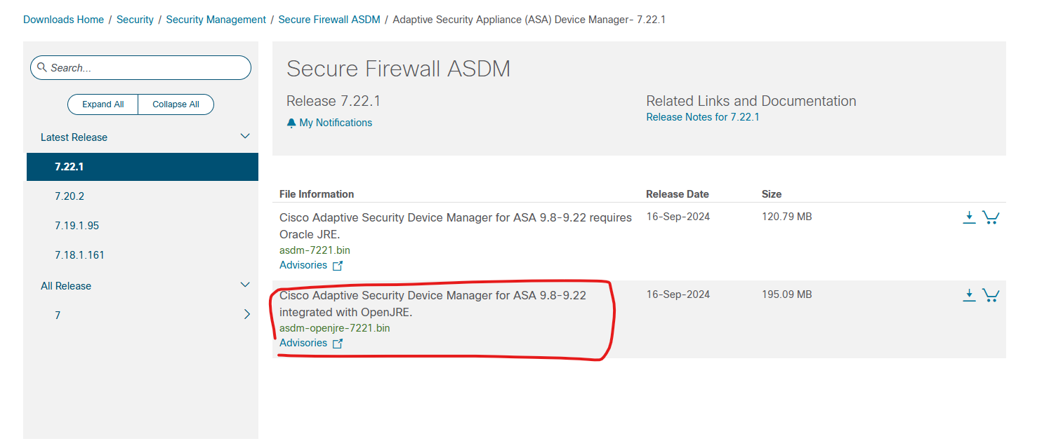
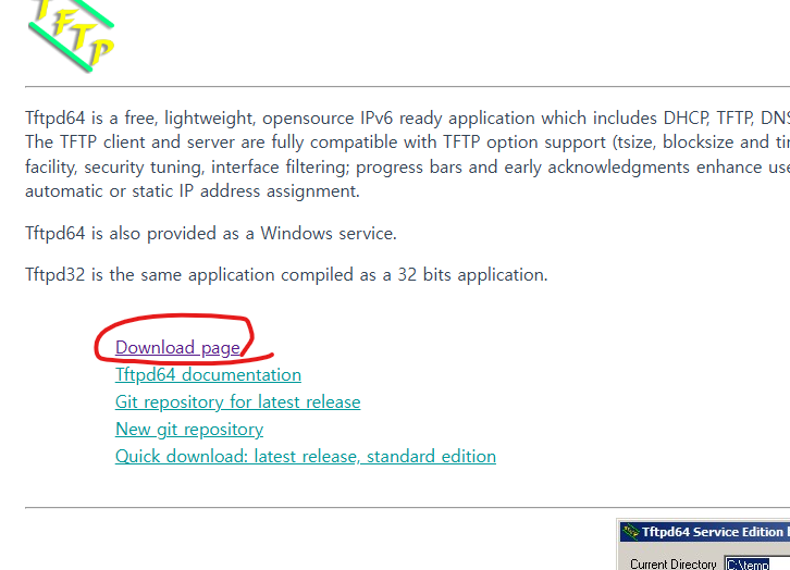
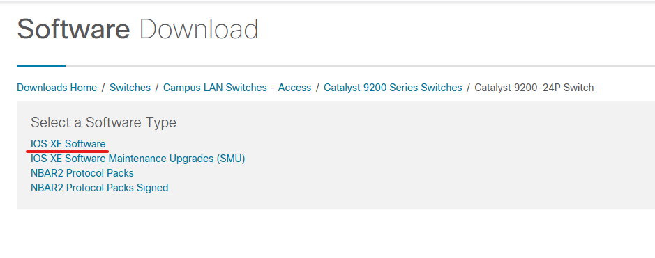
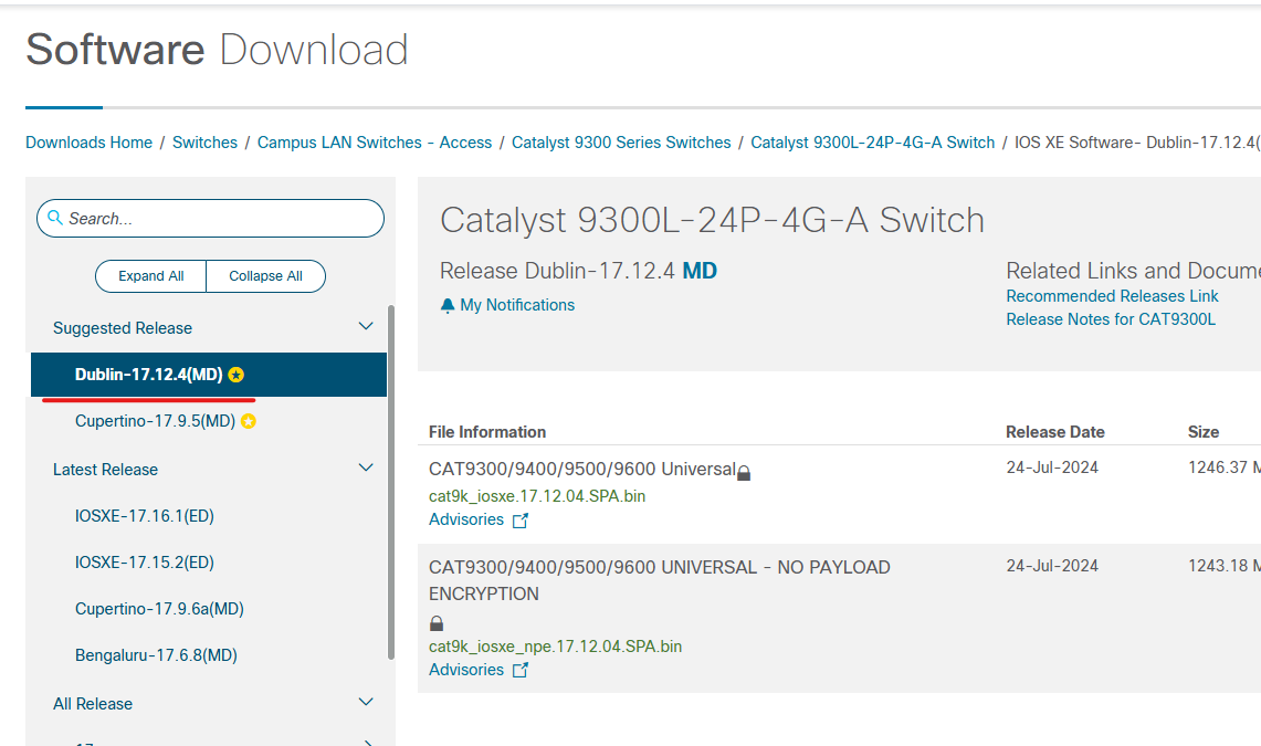
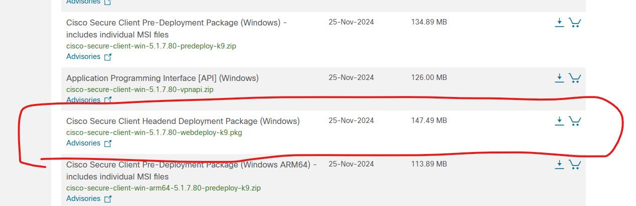
1. Secure Client를 다운로드 받습니다. pkg 확장자입니다.
https://software.cisco.com/download/home/286330811/type/282364313/release/5.1.7.80
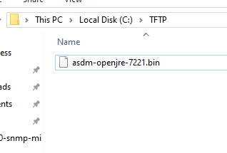
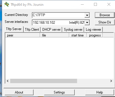
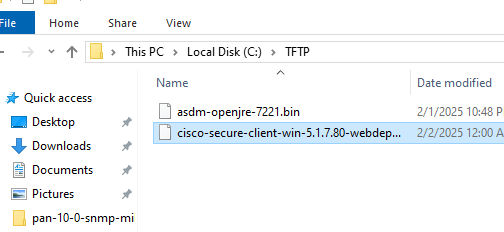
2. 다운로드 파일을 TFTP 폴더에 복사 합니다.
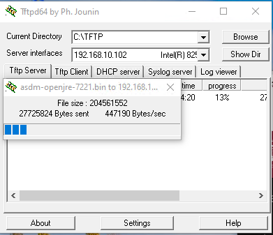
3. 이 파일을 cisco ASA에 업로드 합니다.
| ASAv# copy tftp flash Address or name of remote host []? 192.168.10.102 Source filename []? cisco-secure-client-win-5.1.7.80-webdeploy-k9.pkg Destination filename [cisco-secure-client-win-5.1.7.80-webdeploy-k9.pkg]? Accessing tftp://192.168.10.102/cisco-secure-client-win-5.1.7.80-webdeploy-k9.pkg...!!! ASAv# dir flash: Directory of disk0:/ 7 -rwx 0 11:39:22 May 21 2017 use_ttyS0 11 drwx 4096 03:12:34 Feb 02 2025 smart-log 8 drwx 4096 03:10:50 Feb 02 2025 log 12 drwx 4096 03:12:40 Feb 02 2025 coredumpinfo 84 -rwx 204561552 07:24:47 Feb 02 2025 asdm-openjre-7221.bin 85 -rwx 154655608 08:11:13 Feb 02 2025 cisco-secure-client-win-5.1.7.80-webdeploy-k9.pkg 8571076608 bytes total (8190124032 bytes free) ASAv# |
4. Cisco Remote Access VPN 설정값입니다.
4-1 Secure Client를 통해서 User가 ASA VPN에 연결 되면 IP주소는 192.168.200.100~ 192.168.200.200 사이에 IP주소를 할당 받습니다.
4-2 SPLIT_TUNNEL 10.1.1.0/24 대역 통신 할때는 VPN에 접속 합니다.
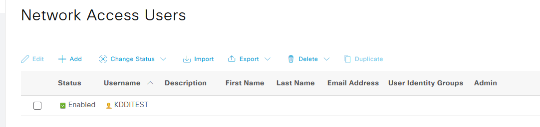
4-3 SSL_USER 계정은 VPN용으로만 사용 가능 합니다.
아래 처럼 그냥 COPY and PASTE하면 cisco ASA Remote Access VPN이 동작 합니다.
| webvpn anyconnect image flash:/cisco-secure-client-win-5.1.7.80-webdeploy-k9.pkg enable outside anyconnect enable http redirect OUTSIDE 80 ip local pool VPN_POOL 192.168.200.100-192.168.200.200 mask 255.255.255.0 access-list SPLIT_TUNNEL standard permit 10.1.1.0 255.255.255.0 access-list SPLIT_TUNNEL standard permit 10.10.10.0 255.255.255.0 group-policy ANYCONNECT_POLICY internal group-policy ANYCONNECT_POLICY attributes vpn-tunnel-protocol ssl-client ssl-clientless split-tunnel-policy tunnelspecified split-tunnel-network-list value SPLIT_TUNNEL dns-server value 8.8.8.8 webvpn anyconnect keep-installer installed anyconnect ask none default anyconnect anyconnect dpd-interval client 30 exit tunnel-group MY_TUNNEL type remote-access tunnel-group MY_TUNNEL general-attributes default-group-policy ANYCONNECT_POLICY address-pool VPN_POOL exit tunnel-group MY_TUNNEL webvpn-attributes group-alias SSL_USERS enable webvpn tunnel-group-list enable username SSL_USER password XXXXXXX username SSL_USER attributes service-type remote-access |
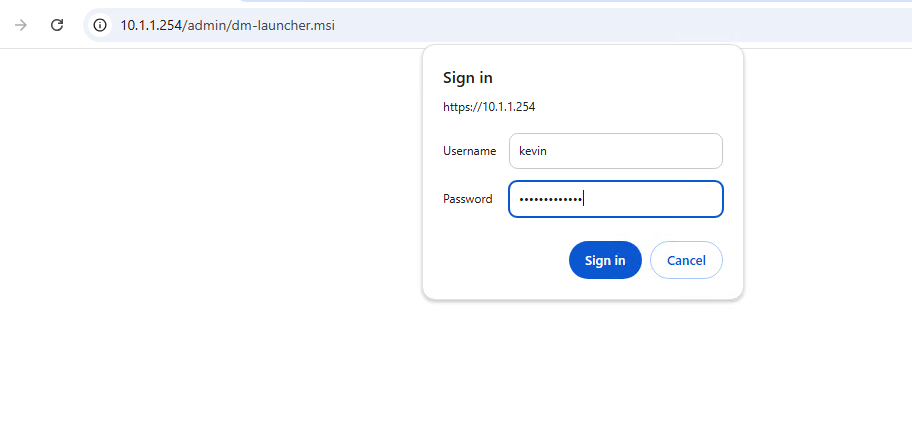
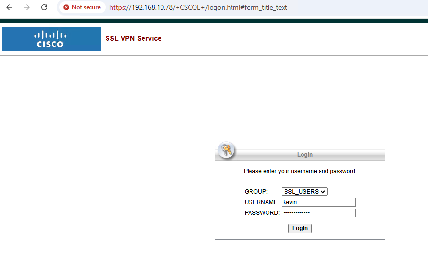
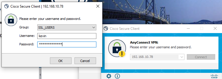
5. https://192.168.10.78 접속 합니다
| ASAv# show nameif Interface Name Security GigabitEthernet0/0 outside 0 GigabitEthernet0/1 inside 100 Management0/0 MGMT 0 ASAv# show int ASAv# show interface ip brie Interface IP-Address OK? Method Status Protocol GigabitEthernet0/0 192.168.10.78 YES manual up up GigabitEthernet0/1 10.1.1.254 YES manual up up GigabitEthernet0/2 unassigned YES unset administratively down down GigabitEthernet0/3 unassigned YES unset administratively down down GigabitEthernet0/4 unassigned YES unset administratively down down GigabitEthernet0/5 unassigned YES unset administratively down down GigabitEthernet0/6 unassigned YES unset administratively down down Management0/0 192.168.100.250 YES manual up up ASAv# |
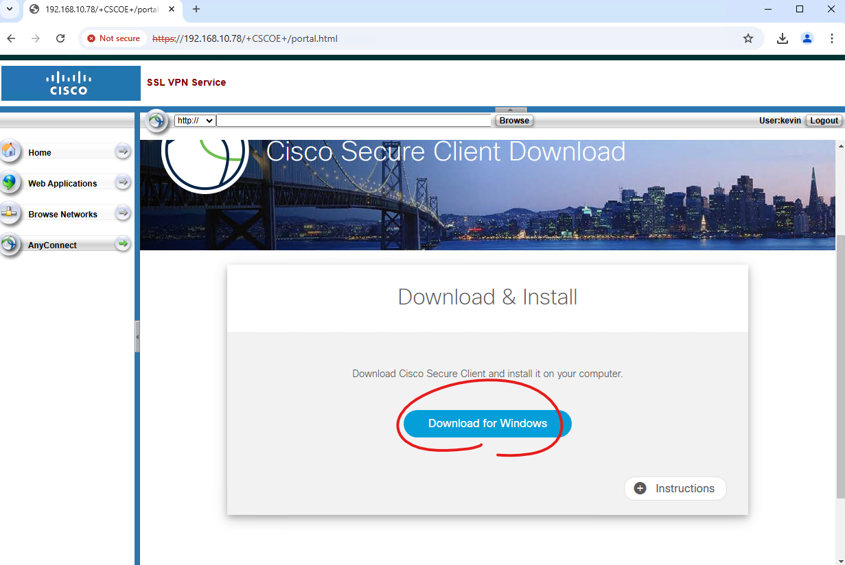
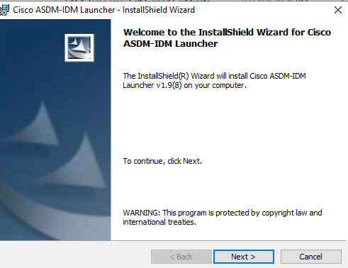
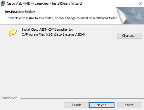
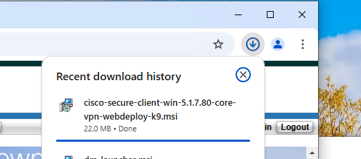
6. Download가 완료되면 설치 합니다. 설치 과정은 생략 하겠습니다.
7. 설치가 완료되면 Cisco Secure Client를 실행해서 접속 합니다.
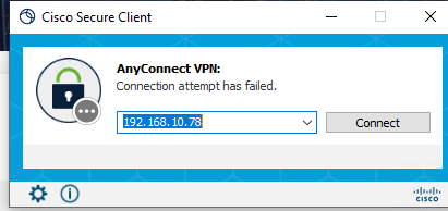
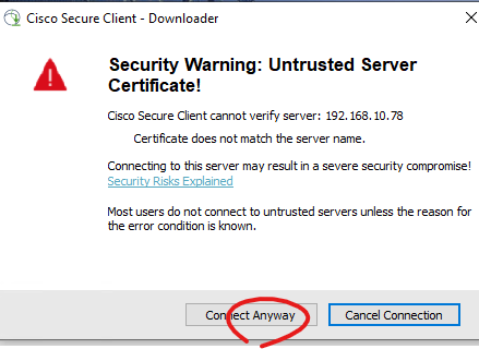
Connect Anyway를 클릭 합니다.
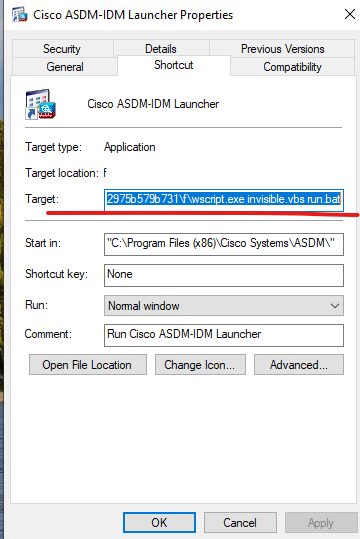
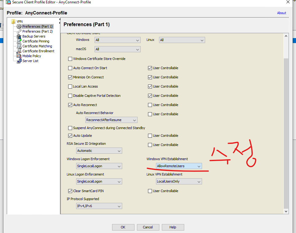
만약에 아래처럼 실행 오류가 나면 아래처럼 추가적으로 설정이 필요합니다.
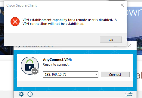
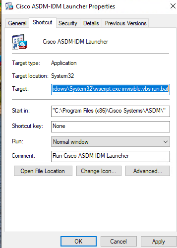
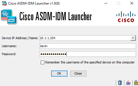
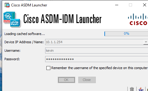
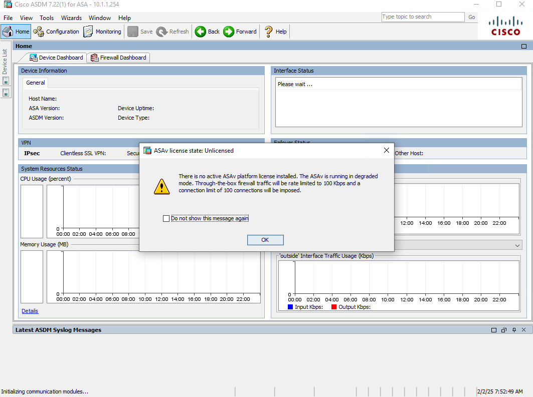
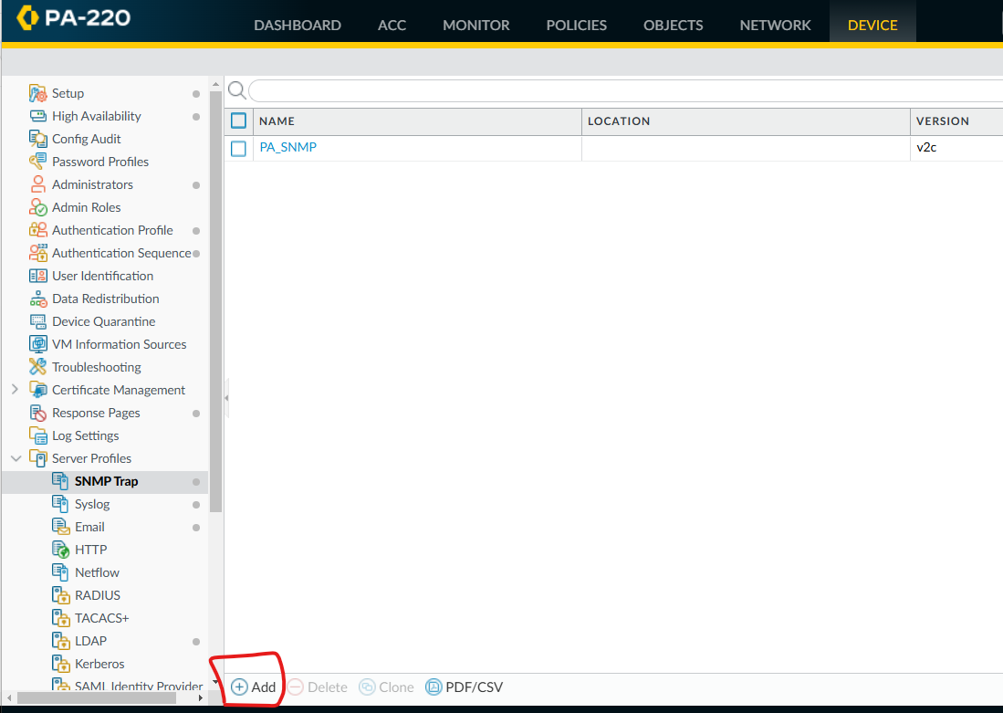
ASDM 에 접속해서 아래처럼 접속합니다.
Remote-Access VPN -> Network Client Access -> Secure Client Profile -> Add
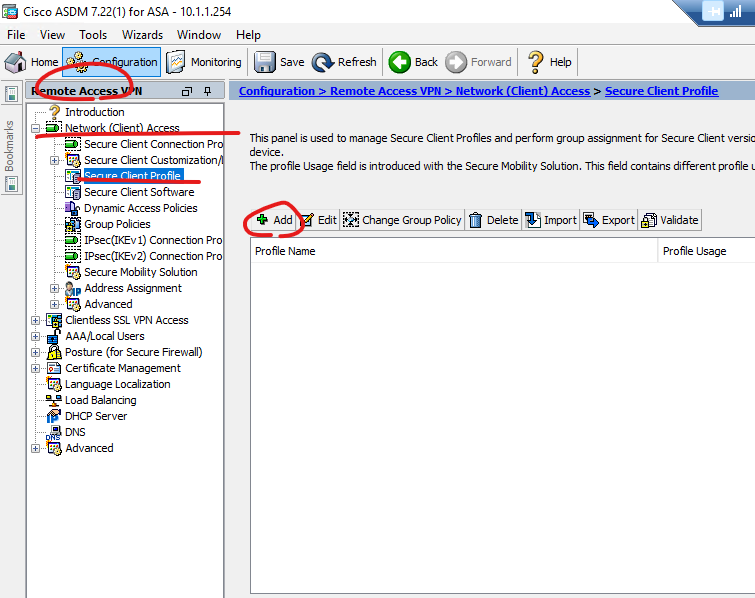
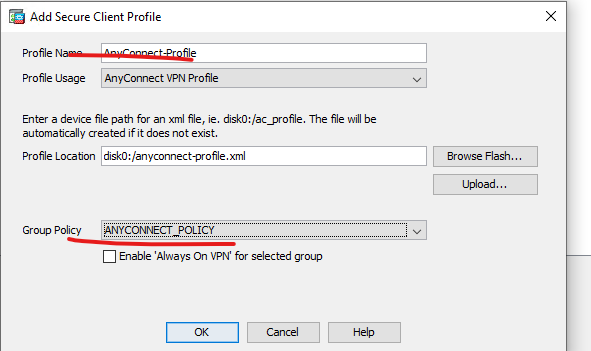
아래처럼 LocalUserOnly -> AllowRemoteUser로 수정 합니다.
다시 접속을 시도 합니다.
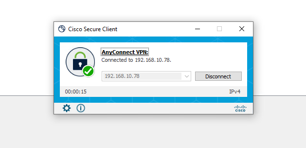
정상적으로 접속 되었습니다.
Remote Access User가 VPN통해서 내부에 있는 자원에 통신 할려고 방화벽 정책이 필요 합니다.
G0/0 outside - ACL name - outsideacl
G0/1 inside - ACL name - insideacl
G0/2 DMZ - ACL name -dmzacl
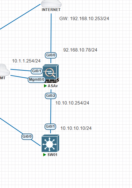
| ASAv# show interface ip brie Interface IP-Address OK? Method Status Protocol GigabitEthernet0/0 192.168.10.78 YES manual up up GigabitEthernet0/1 10.1.1.254 YES manual up up GigabitEthernet0/2 10.10.10.254 YES manual up up GigabitEthernet0/3 unassigned YES unset administratively down down GigabitEthernet0/4 unassigned YES unset administratively down down GigabitEthernet0/5 unassigned YES unset administratively down down GigabitEthernet0/6 unassigned YES unset administratively down down Management0/0 192.168.100.250 YES manual up up ASAv# |
SW 설정
| interface GigabitEthernet0/1 no switchport ip address 10.10.10.10 255.255.255.0 negotiation auto ip route 0.0.0.0 0.0.0.0 10.10.10.254 |
방화벽 정책 설정
| ASAv(config)# access-list outsideacl extended permit ip 192.168.200.0 255.255.255.0 10.10.10.0 255.255.255.0 ASAv(config)# access-group outsideacl in interface outside |
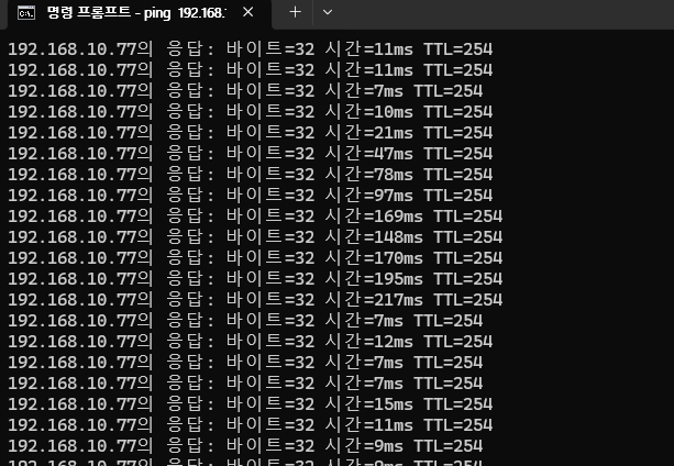
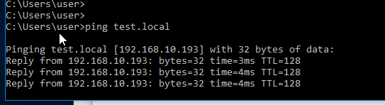
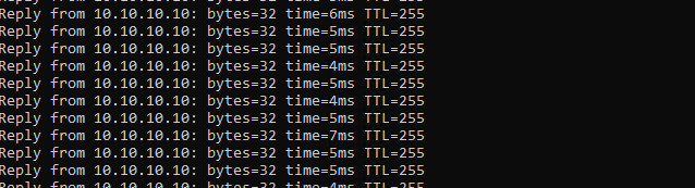
Secure Client 접속후 Ping 10.10.10.10 하면 아래처럼 성공 합니다.
| ASAv# show access-list access-list cached ACL log flows: total 1, denied 1 (deny-flow-max 4096) alert-interval 300 access-list SPLIT_TUNNEL; 2 elements; name hash: 0x63aa8f22 access-list SPLIT_TUNNEL line 1 standard permit 10.1.1.0 255.255.255.0 (hitcnt=0) 0x96d75e6a access-list SPLIT_TUNNEL line 2 standard permit 10.10.10.0 255.255.255.0 (hitcnt=0) 0x23138585 access-list outsideacl; 1 elements; name hash: 0x945119d1 access-list outsideacl line 1 extended permit ip 192.168.200.0 255.255.255.0 10.10.10.0 255.255.255.0 (hitcnt=1) 0xb46d0730 ASAv# |
만약에 Remote Access VPN USER들은 outbound access-list 없이 그냥 BYpass하고 싶으면 아래 명령어를 입력합니다.
| ASA1(config)# sysopt connection permit-vpn |
지금까지 [ASA #04] - Remote Access VPN 글을 읽어주셔서 감사합니다.
'CISCO > ASA 방화벽' 카테고리의 다른 글
| [ASA #06] - Remote Access VPN current user check (0) | 2025.02.02 |
|---|---|
| [ASA #05] - Remote Access VPN License (0) | 2025.02.02 |
| [ASA #03] - ASDM Install (0) | 2025.02.02 |
| [ASA #02] - TFTP Install (0) | 2025.02.02 |
| [ASA #01] - Basic Config (0) | 2025.02.02 |