password: bcpb+serial number -bcpbFGT61E4QXXXXXXXX
serial 정보는 부팅할때 serial number를 확인 가능하고 또는 장비에서 뒷면에서 시리얼번호를 확인 가능 합니다.
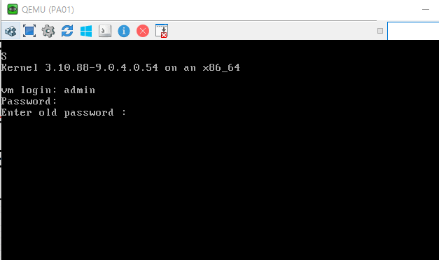
FortiGate-61E (19:30-06.08.2016) Ver:05000009 Serial number: FGT61E4QXXXXXX CPU: 1000MHz Total RAM: 2 GB Initializing boot device... Initializing MAC... nplite#0 Please wait for OS to boot, or press any key to display configuration menu......
WARNING: File System Check Recommended! Unsafe reboot may have caused inconsistency in disk drive. It is strongly recommended that you check file system consistency before proceeding. Please run 'execute disk scan 259' Note: The device will reboot and scan during startup. This may take up to an hour
WARNING: File System Check Recommended! Unsafe reboot may have caused inconsistency in disk drive. It is strongly recommended that you check file system consistency before proceeding. Please run 'execute disk scan 259' Note: The device will reboot and scan during startup. This may take up to an hour FW1 #
지금까지 fortigate 방화벽 Password Recovery에 대해서 알아보았습니다.
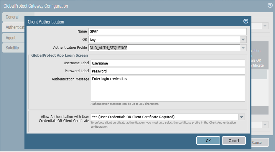
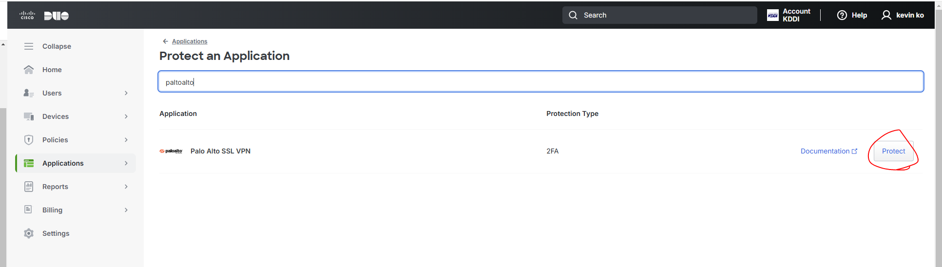
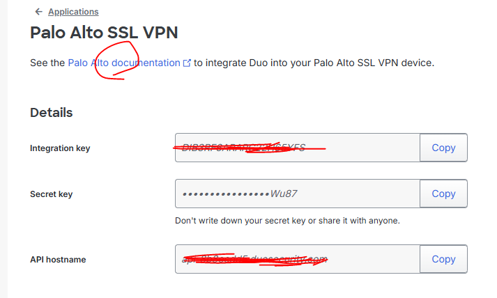
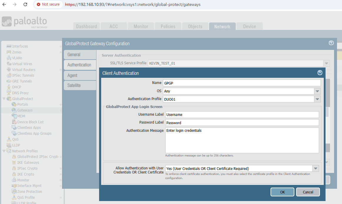
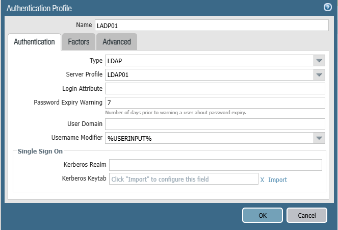
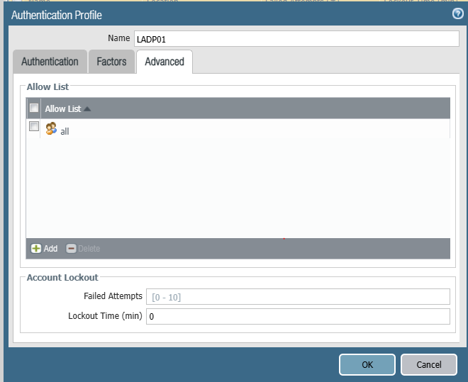
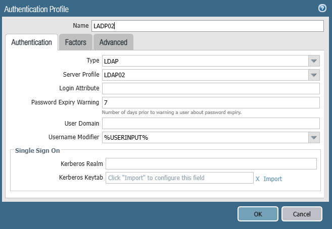
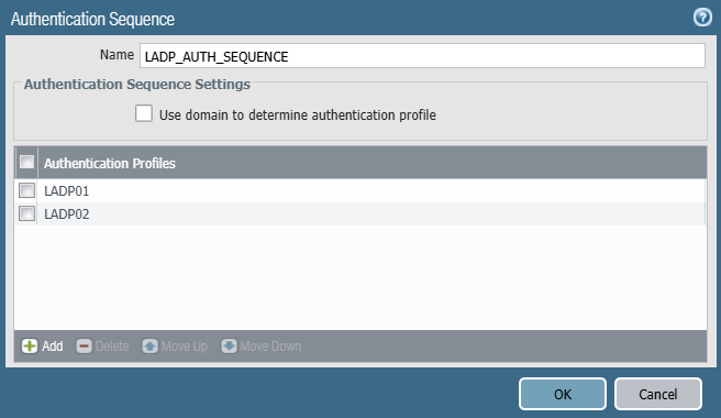
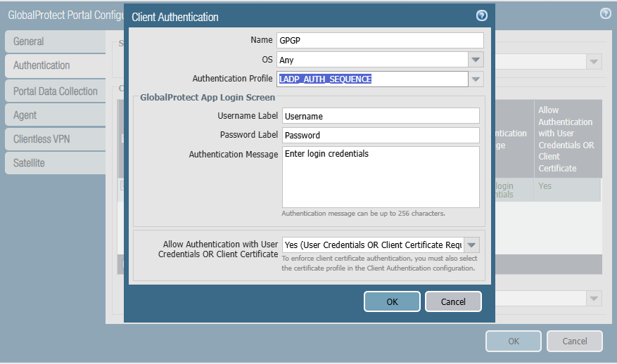
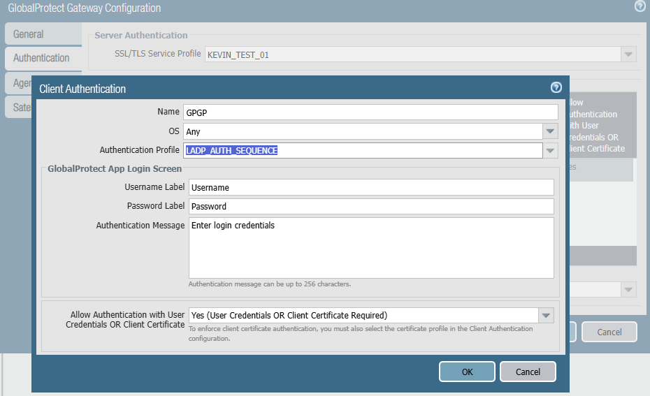
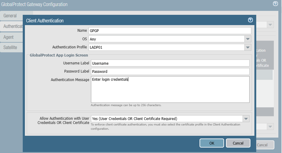
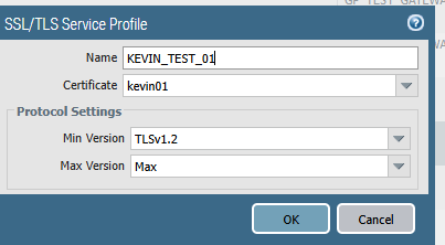
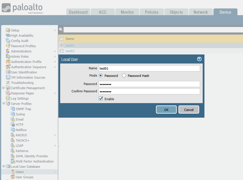
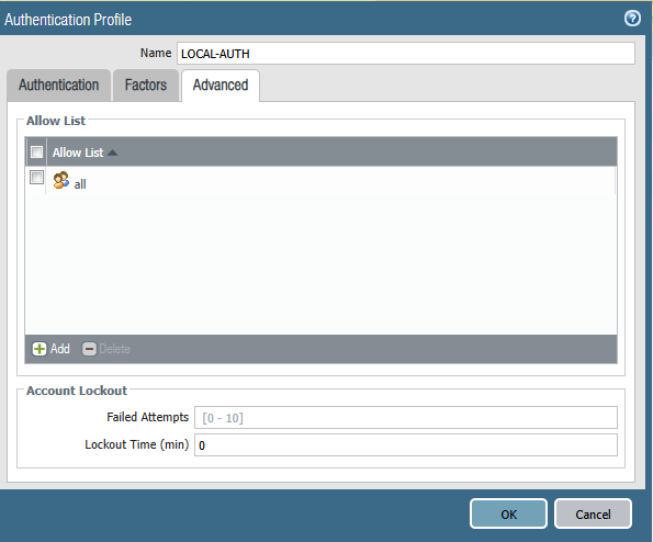
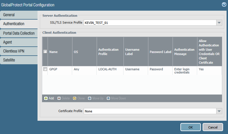
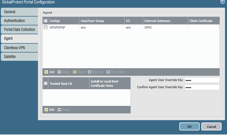
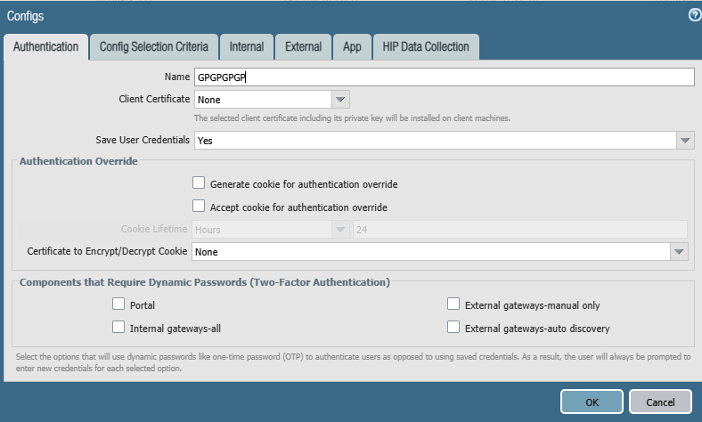
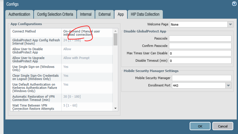
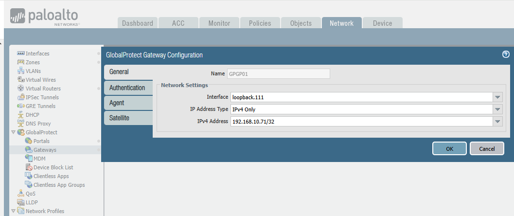
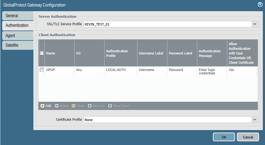
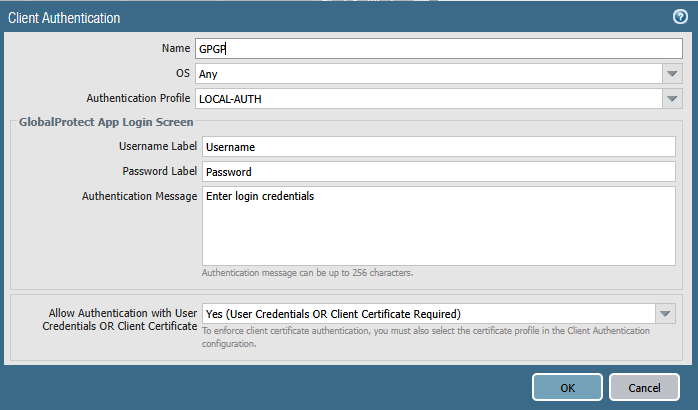
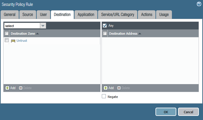
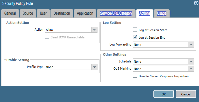
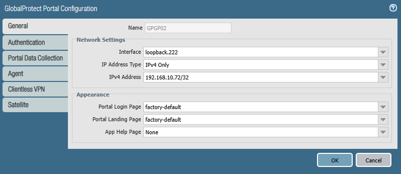
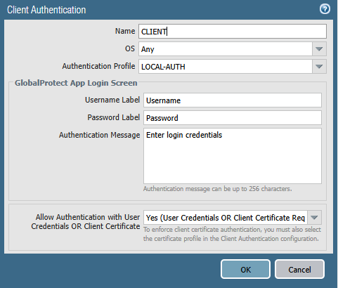
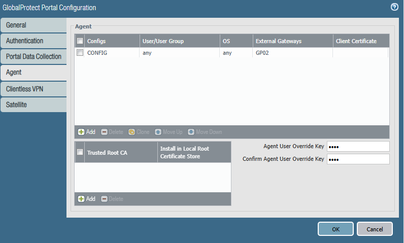
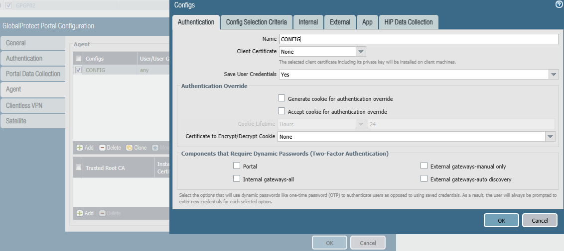
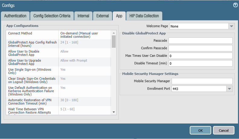
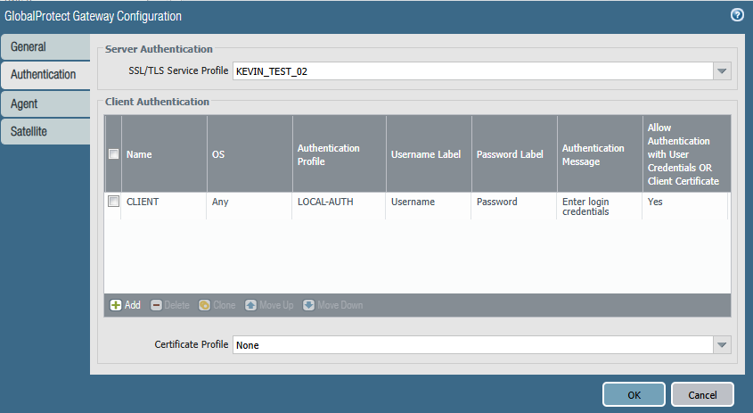
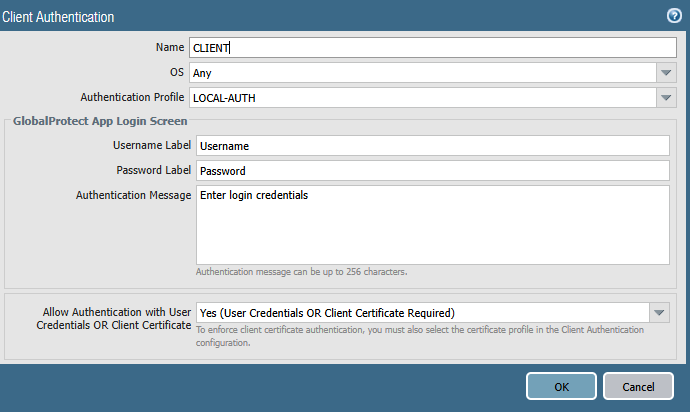
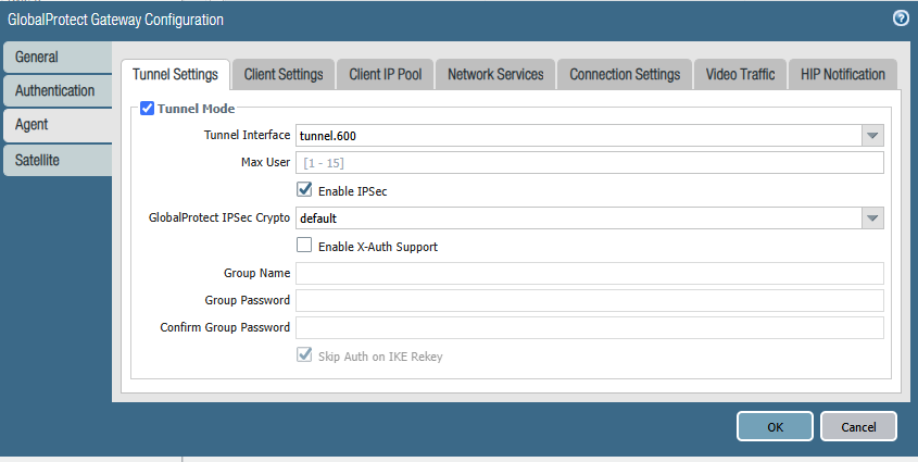
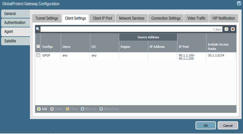
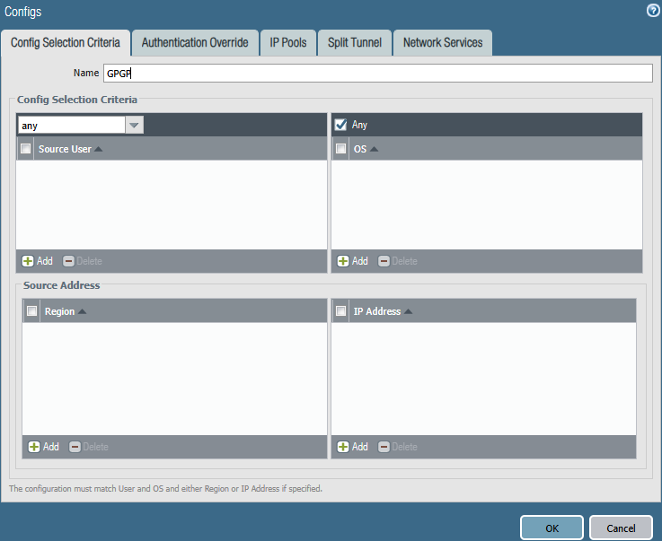
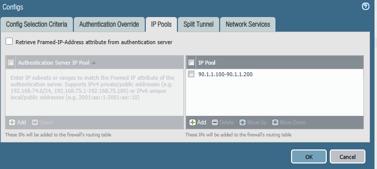
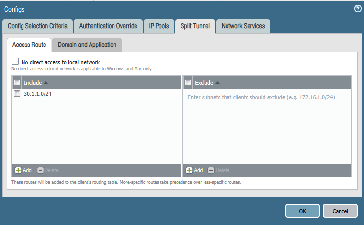
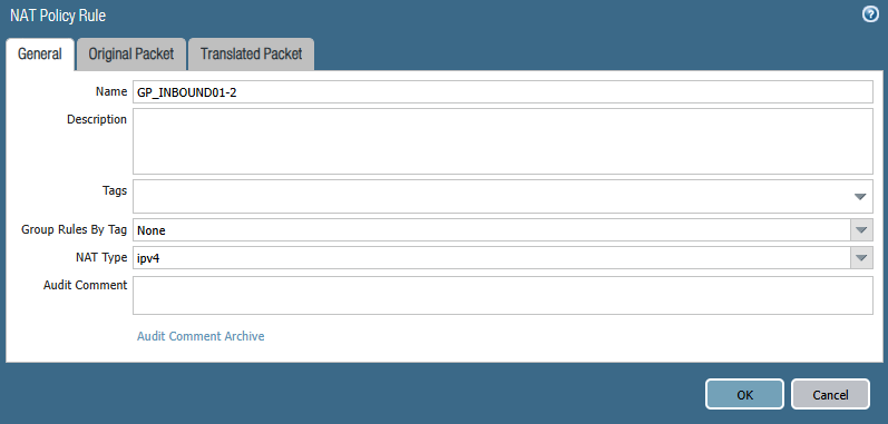
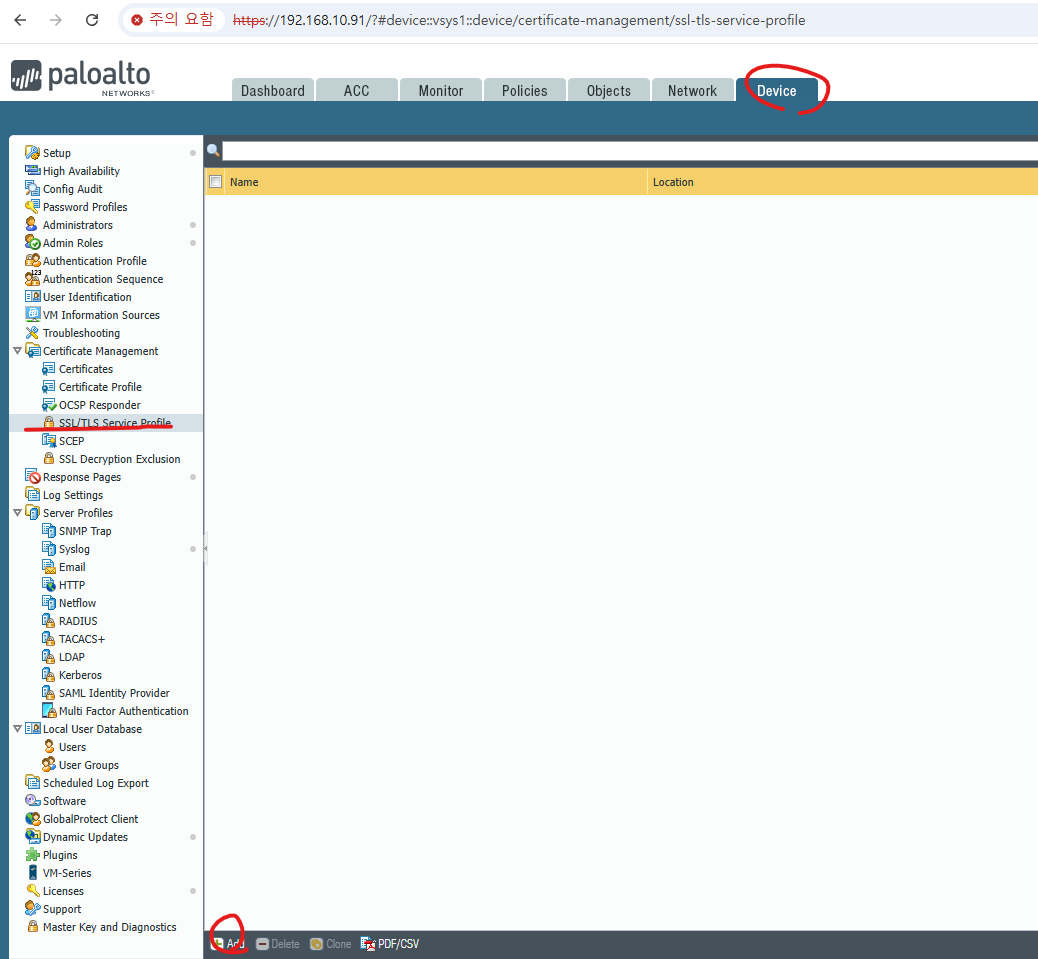
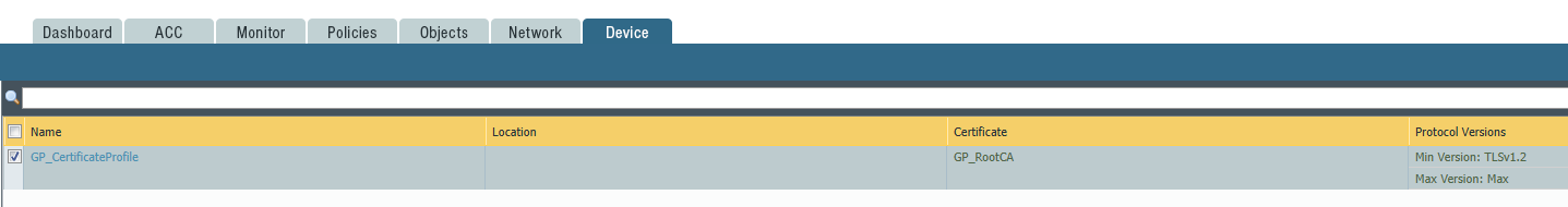
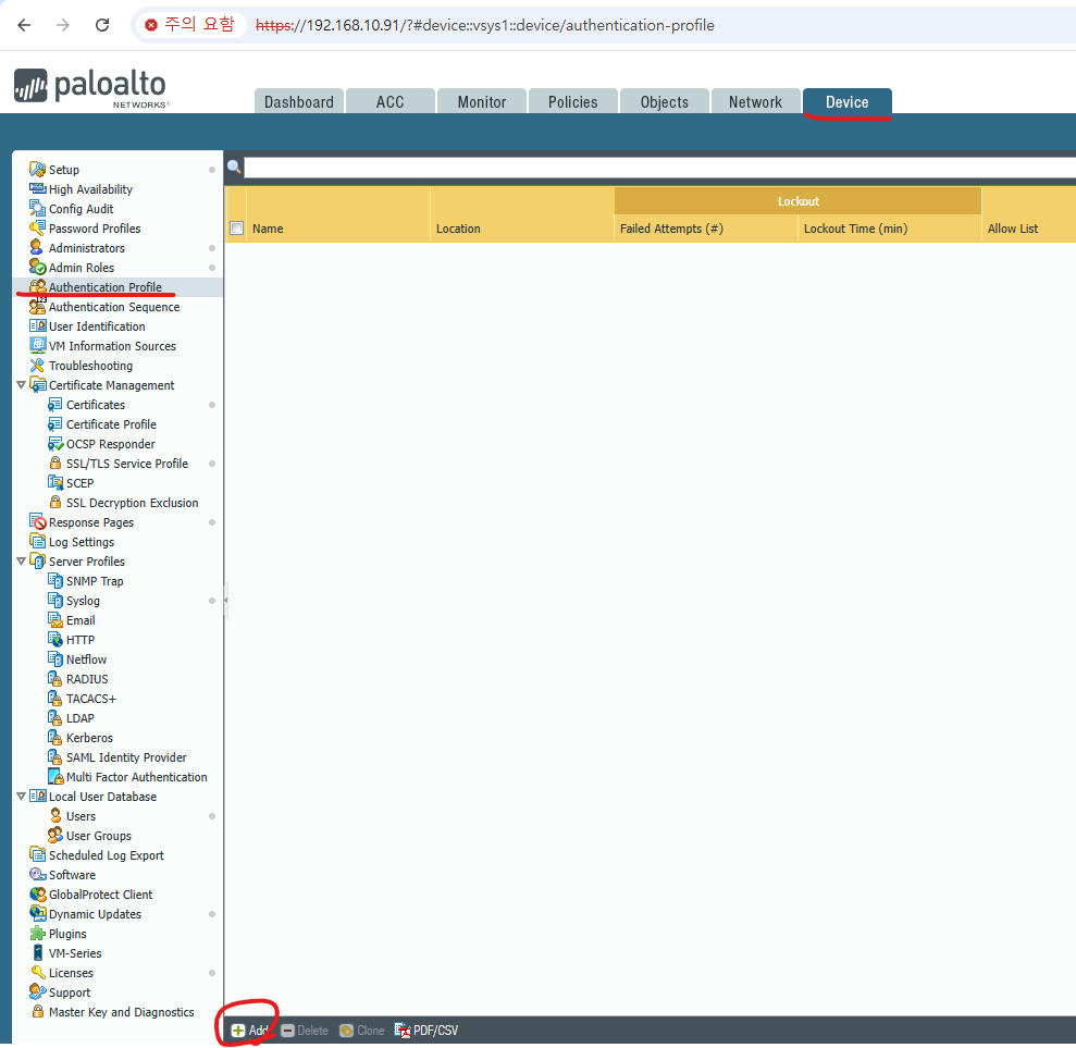
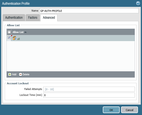
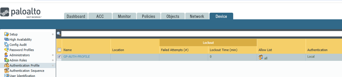
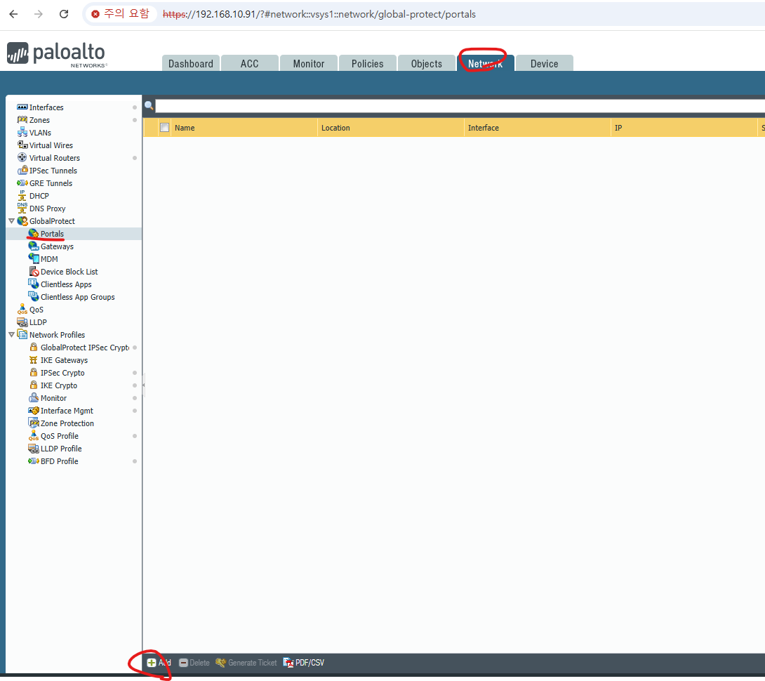
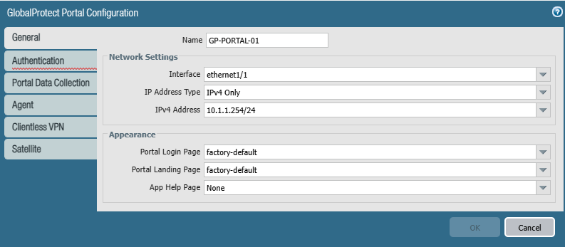
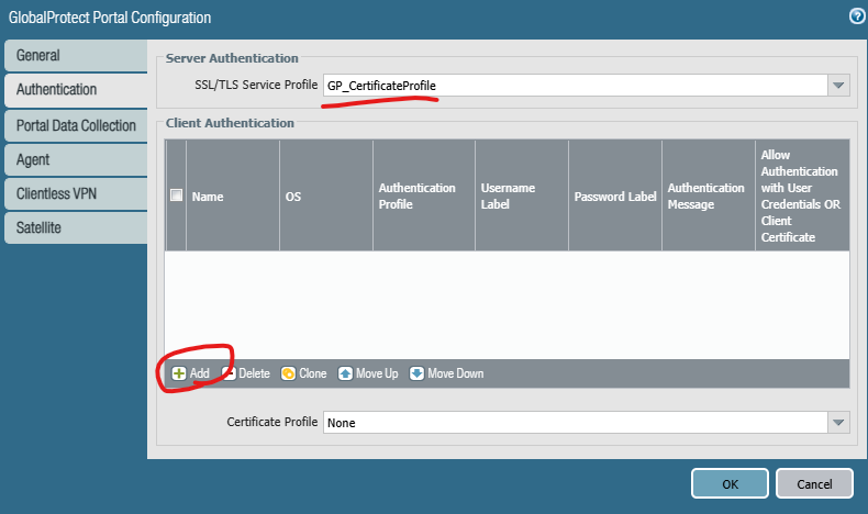
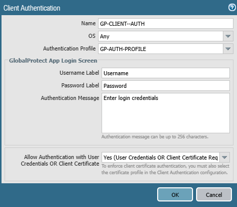
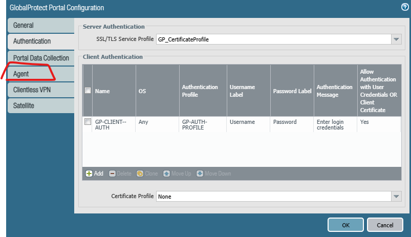
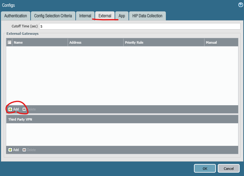
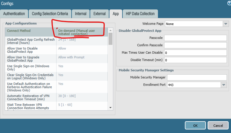
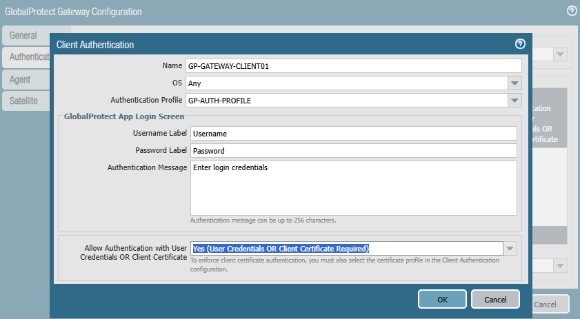
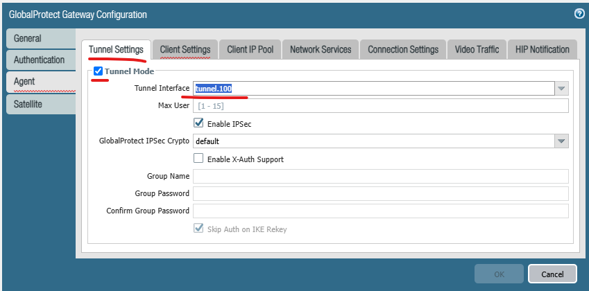
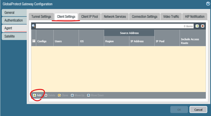
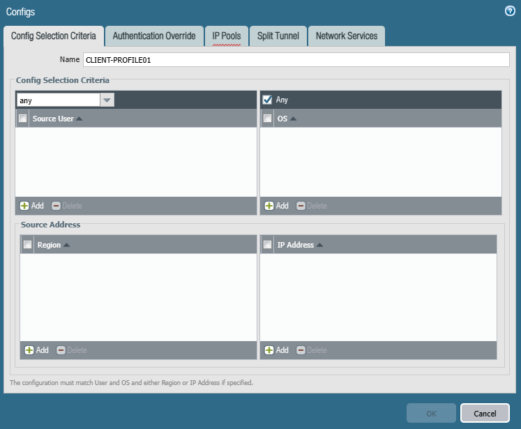
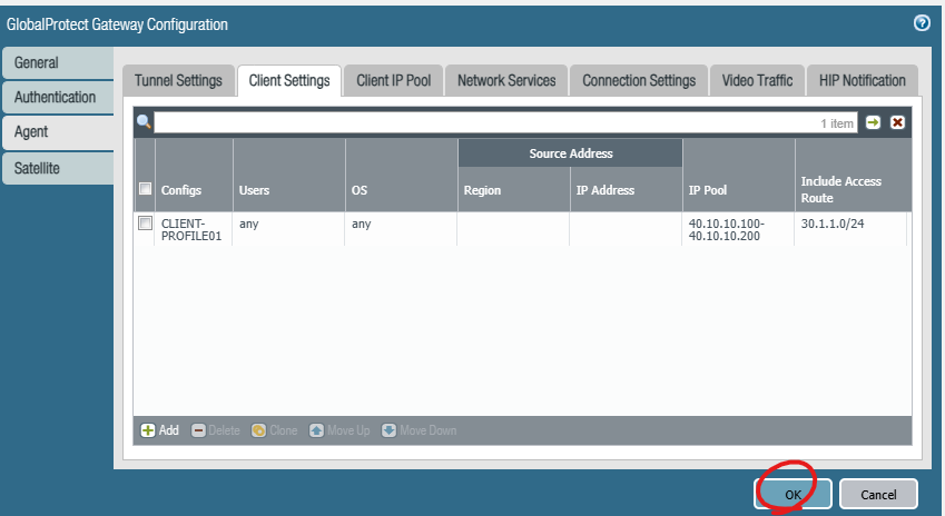
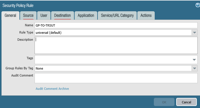
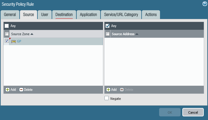
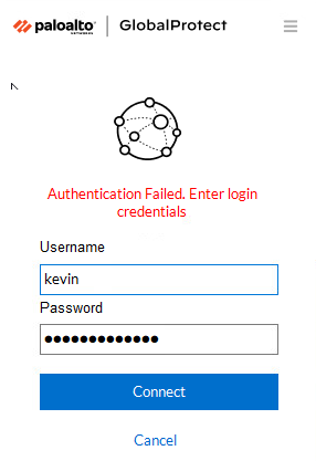
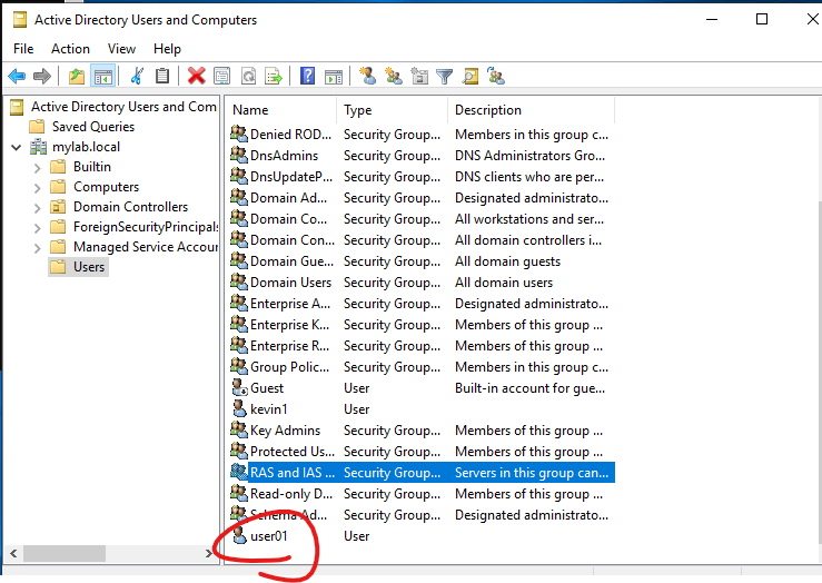
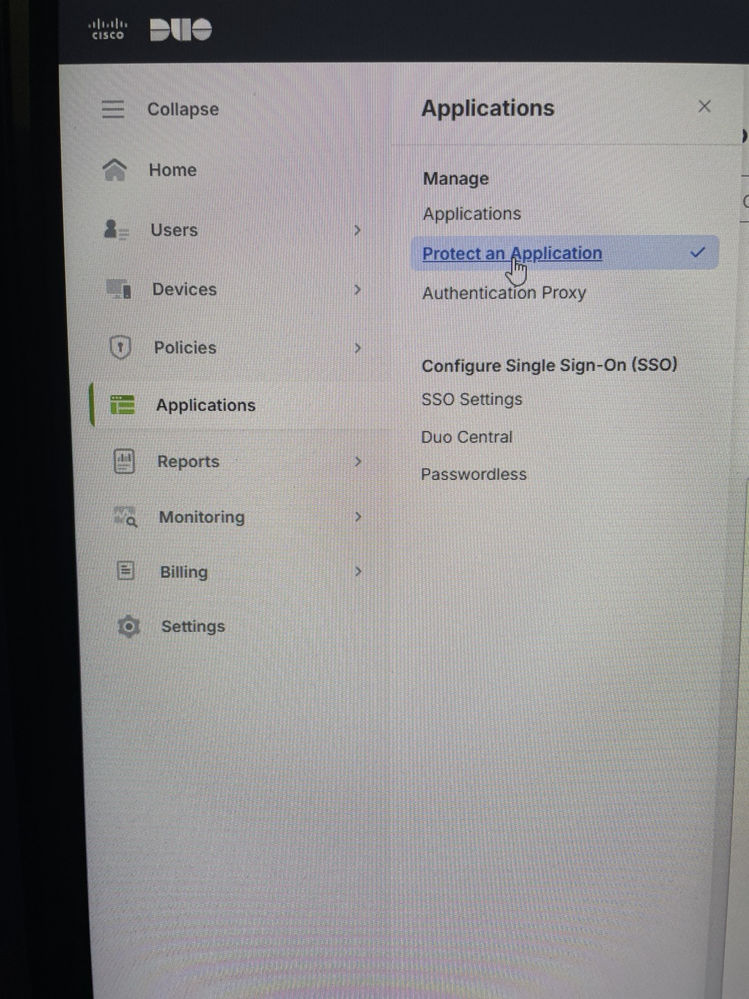
4. Global Protect Gateway에서 Authentication 수정 합니다.
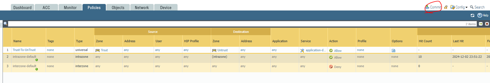
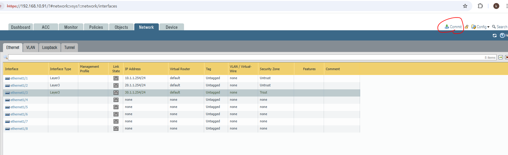
그리고 Commit를 실행합니다.
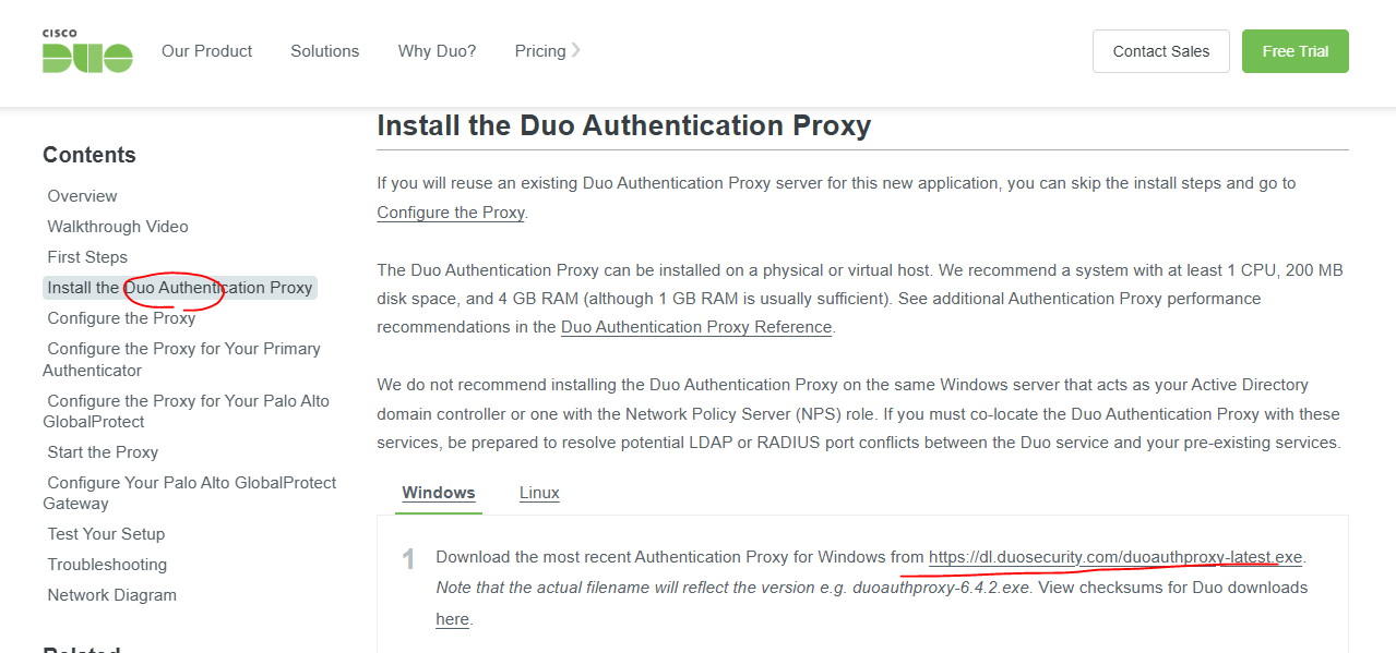
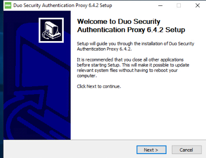
5. PaloAlto SSH로 연결 합니다.
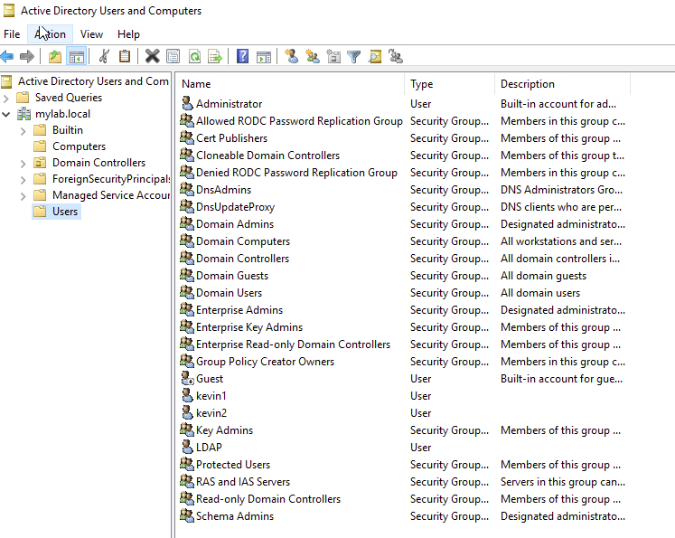
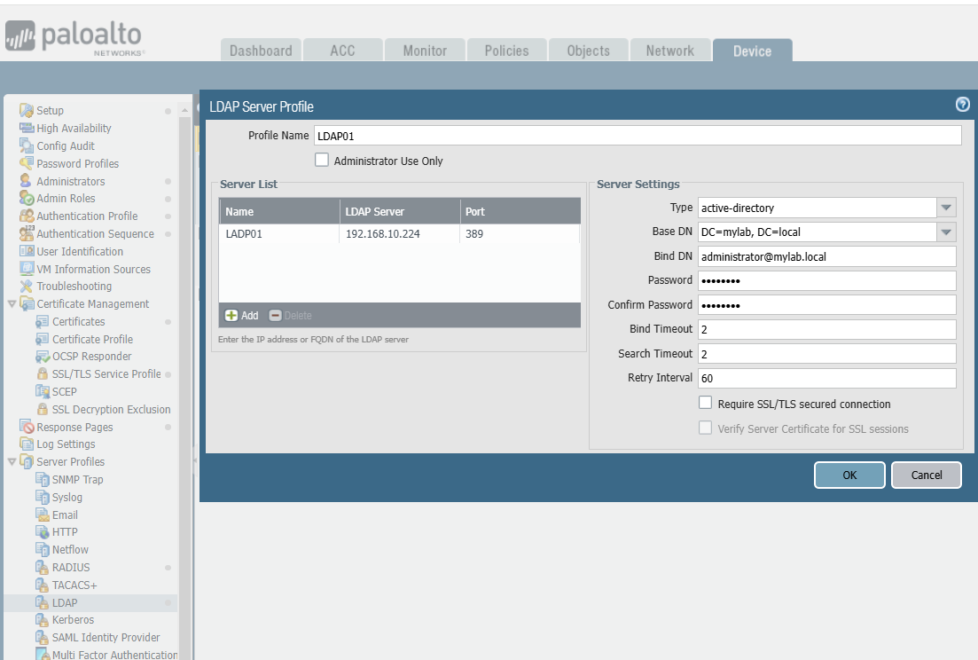
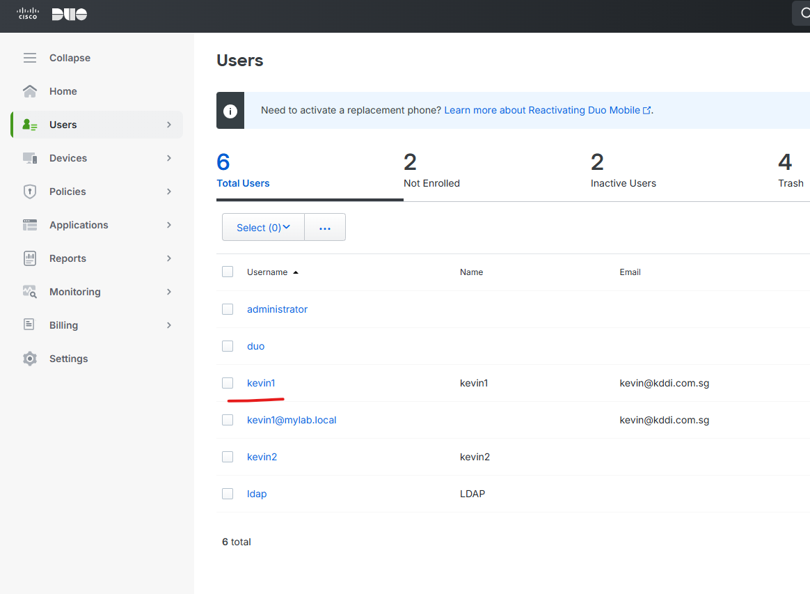
admin@PA-VM> test authentication authentication-profile LADP01 username kevin1 password Enter password :
Target vsys is not specified, user "kevin1" is assumed to be configured with a shared auth profile.
Do allow list check before sending out authentication request... name "kevin1" is in group "all"
Authentication to LDAP server at 192.168.10.224 for user "kevin1" Egress: 192.168.10.93 Type of authentication: plaintext Starting LDAP connection... Succeeded to create a session with LDAP server DN sent to LDAP server: CN=kevin1,CN=Users,DC=mylab,DC=local User expires in days: never
Authentication succeeded for user "kevin1"
admin@PA-VM>
Profile 테스트 했을때 위에 처럼 성공하였습니다.
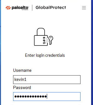
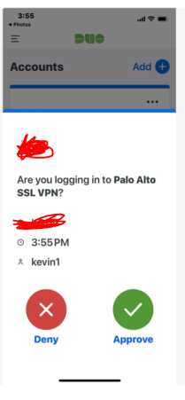
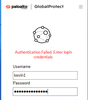
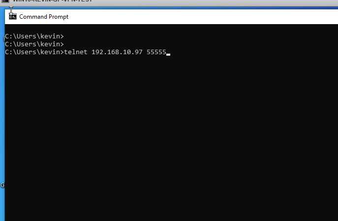
이번에는 GP 프로그램을 이용해서 직접 테스트 해보겠습니다
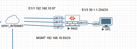
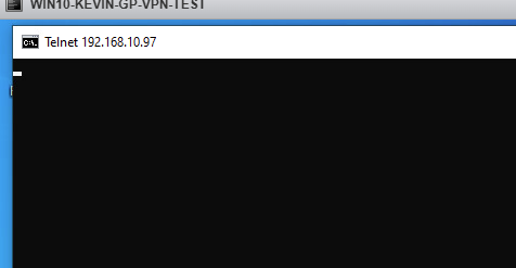
192.168.10.97 55555
연결이 완료 되었습니다
지금까지 Global Protect 인증할때 Active Directory를 사용해서 인증해보았습니다.
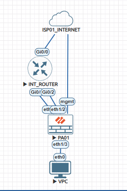
en conf t ho INT_Router int g0/0 ip add 192.168.10.92 255.255.255.0 no sh int g0/1 ip add 10.1.1.1 255.255.255.0 no sh int g0/2 ip add 20.1.1.1 255.255.255.0 no sh ip route 0.0.0.0 0.0.0.0 192.168.10.253
2. Check INT_Router
Router#show ip int brie Interface IP-Address OK? Method Status Protocol GigabitEthernet0/0 192.168.10.92 YES manual up up GigabitEthernet0/1 10.1.1.1 YES manual up up GigabitEthernet0/2 20.1.1.1 YES manual up up GigabitEthernet0/3 unassigned YES unset administratively down down Router#
Router#show ip route Codes: L - local, C - connected, S - static, R - RIP, M - mobile, B - BGP D - EIGRP, EX - EIGRP external, O - OSPF, IA - OSPF inter area N1 - OSPF NSSA external type 1, N2 - OSPF NSSA external type 2 E1 - OSPF external type 1, E2 - OSPF external type 2 i - IS-IS, su - IS-IS summary, L1 - IS-IS level-1, L2 - IS-IS level-2 ia - IS-IS inter area, * - candidate default, U - per-user static route o - ODR, P - periodic downloaded static route, H - NHRP, l - LISP a - application route + - replicated route, % - next hop override, p - overrides from PfR
Gateway of last resort is 192.168.10.253 to network 0.0.0.0
S* 0.0.0.0/0 [1/0] via 192.168.10.253 10.0.0.0/8 is variably subnetted, 2 subnets, 2 masks C 10.1.1.0/24 is directly connected, GigabitEthernet0/1 L 10.1.1.1/32 is directly connected, GigabitEthernet0/1 20.0.0.0/8 is variably subnetted, 2 subnets, 2 masks C 20.1.1.0/24 is directly connected, GigabitEthernet0/2 L 20.1.1.1/32 is directly connected, GigabitEthernet0/2 192.168.10.0/24 is variably subnetted, 2 subnets, 2 masks C 192.168.10.0/24 is directly connected, GigabitEthernet0/0 L 192.168.10.92/32 is directly connected, GigabitEthernet0/0 Router#
3. ping 8.8.8.8
Router#ping 8.8.8.8 Type escape sequence to abort. Sending 5, 100-byte ICMP Echos to 8.8.8.8, timeout is 2 seconds: !!!!! Success rate is 100 percent (5/5), round-trip min/avg/max = 3/3/4 ms Router#
4. INT_Router에서 SNAT를 설정 합니다.
int g0/0 ip nat outside int g0/1 ip nat inside int g0/2 ip nat inside
access-list 1 permit any ip nat inside source list 1 interface g0/0 overload
5. Test - Source를 변경해서 외부로 Ping를 하면 제대로 동작 합니다.
INT_ROUTER#ping 8.8.8.8 source g0/1 Type escape sequence to abort. Sending 5, 100-byte ICMP Echos to 8.8.8.8, timeout is 2 seconds: Packet sent with a source address of 10.1.1.1 !!!!! Success rate is 100 percent (5/5), round-trip min/avg/max = 3/3/5 ms INT_ROUTER#ping 8.8.8.8 source g0/2 Type escape sequence to abort. Sending 5, 100-byte ICMP Echos to 8.8.8.8, timeout is 2 seconds: Packet sent with a source address of 20.1.1.1 !!!!! Success rate is 100 percent (5/5), round-trip min/avg/max = 3/3/7 ms INT_ROUTER#
6. Router에서 NAT table test
INT_ROUTER#show ip nat translations Pro Inside global Inside local Outside local Outside global icmp 192.168.10.92:3 10.1.1.1:3 8.8.8.8:3 8.8.8.8:3 icmp 192.168.10.92:4 20.1.1.1:4 8.8.8.8:4 8.8.8.8:4 INT_ROUTER#
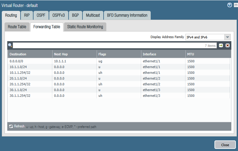
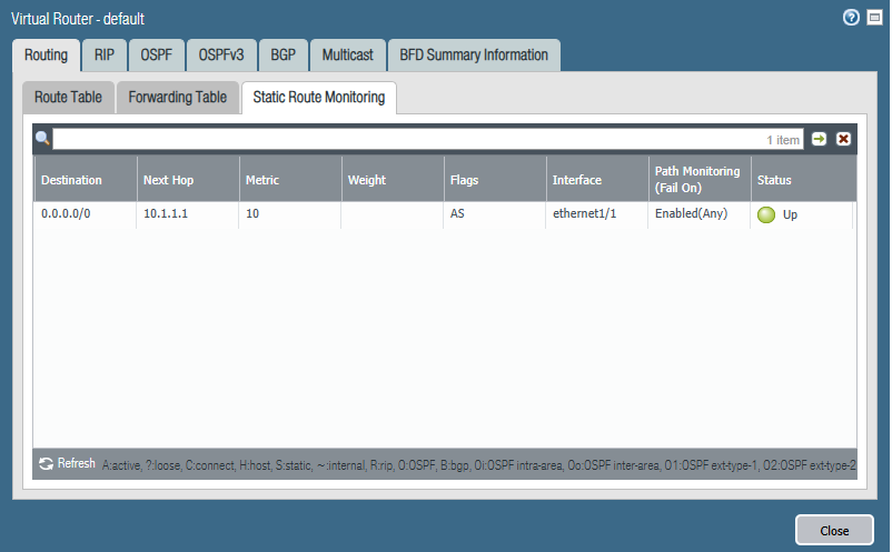
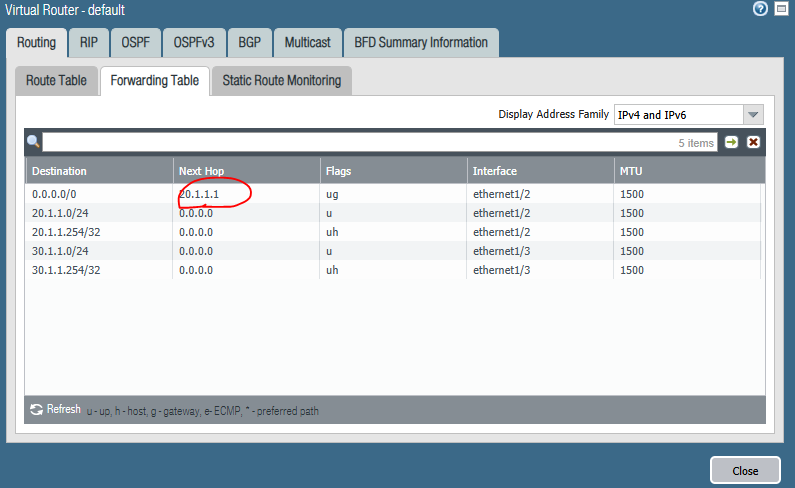
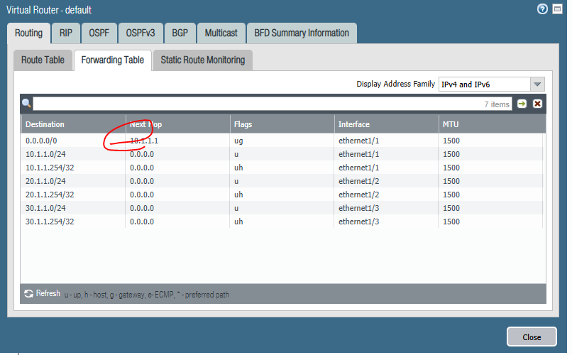
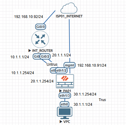
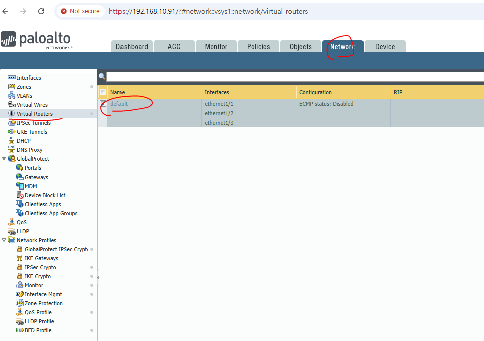
이제 PaloAlto에서 확인해보겠습니다.
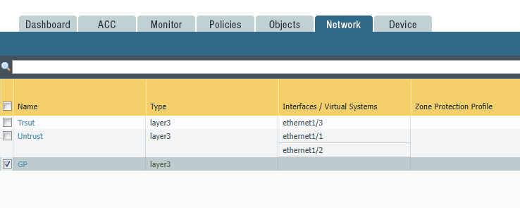
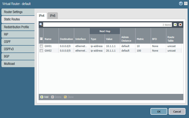
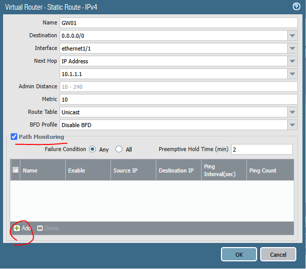
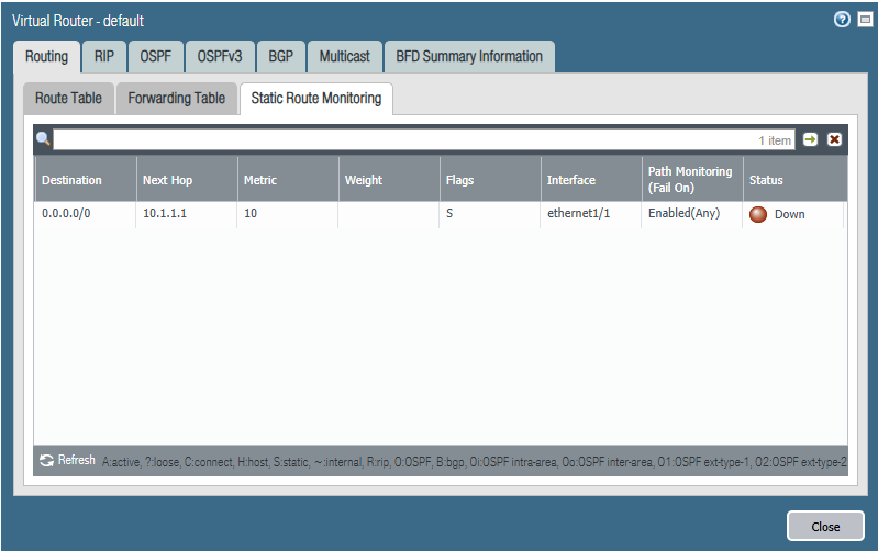
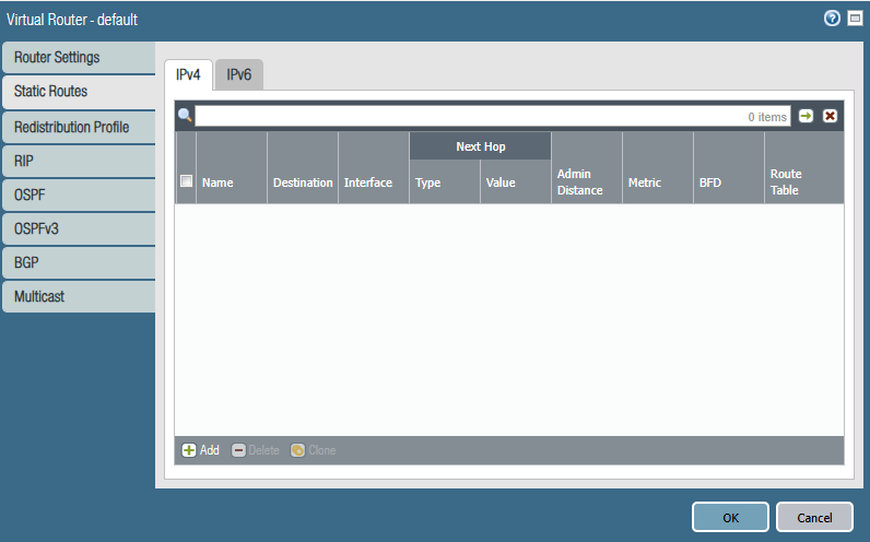
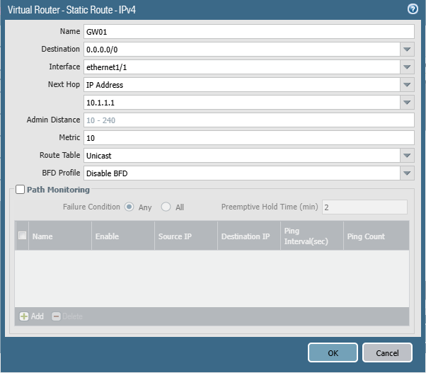
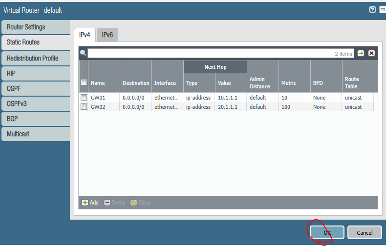
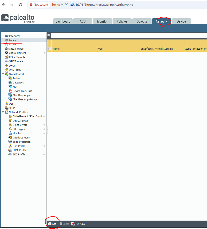
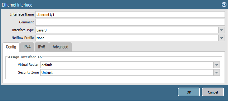
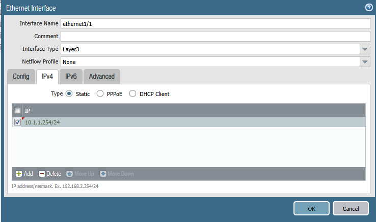
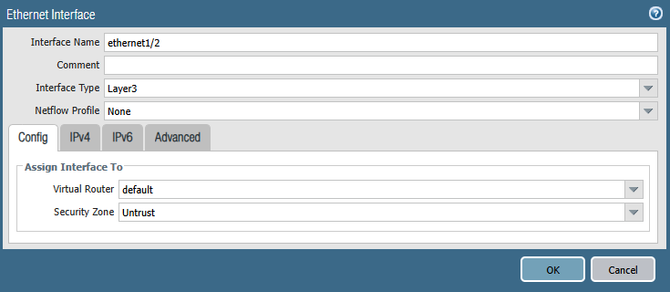
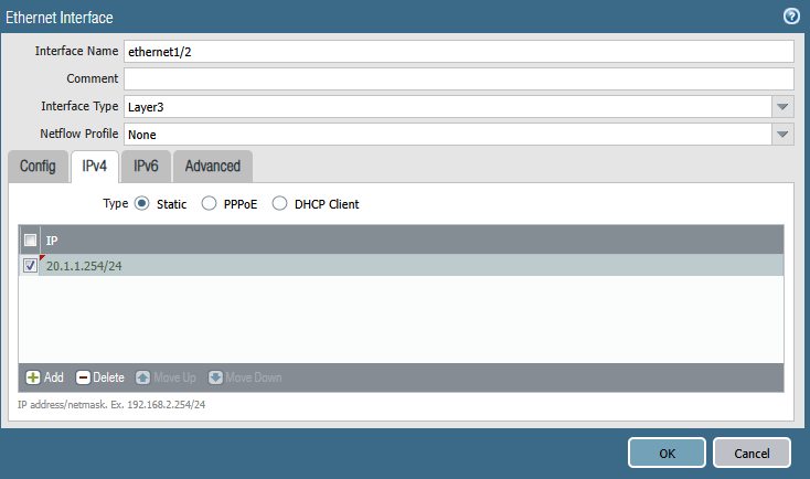
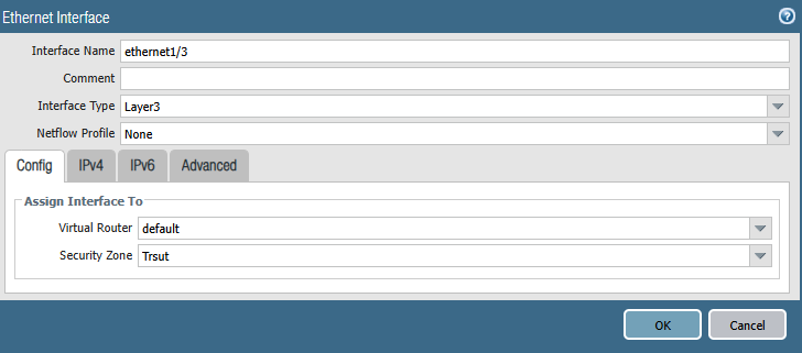
1. Static route를 설정합니다.
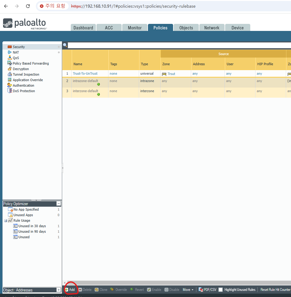
2. Add를 클릭 합니다.
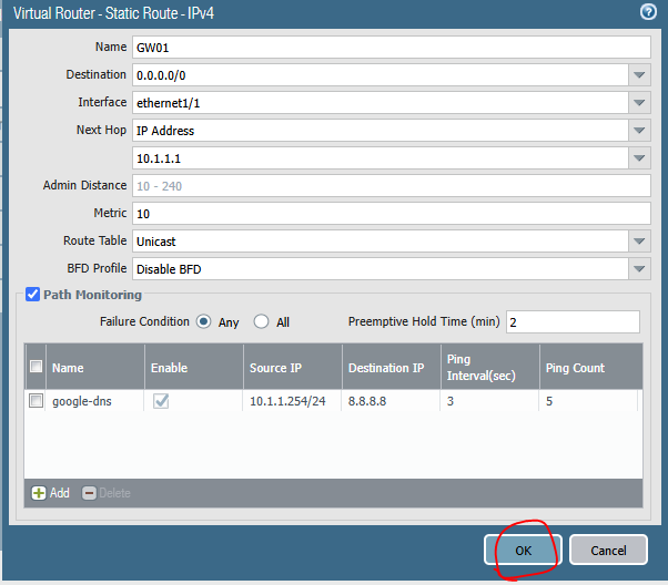
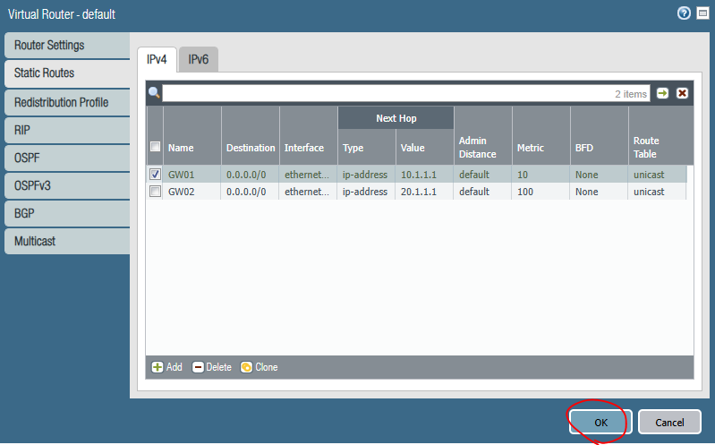
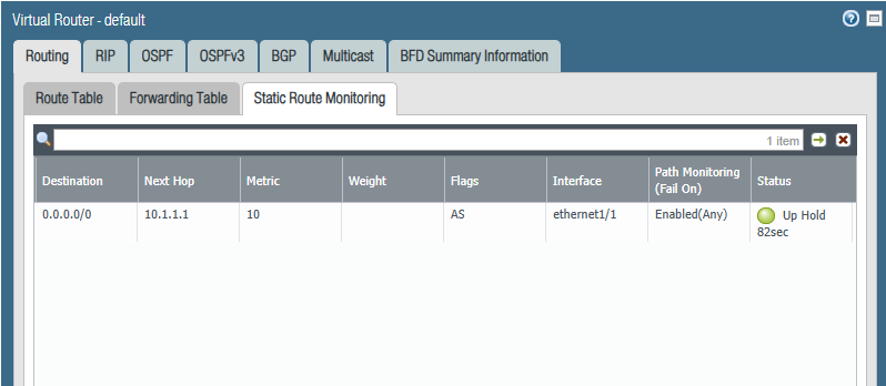
3. GW01를 설정합니다. Metric 10
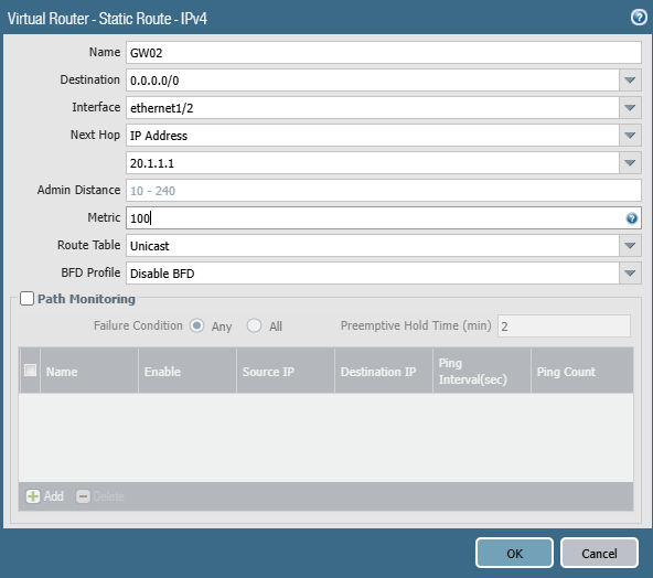
4. GW02를 설정합니다.
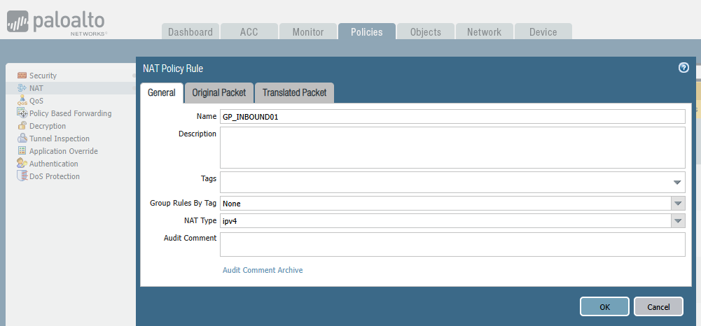
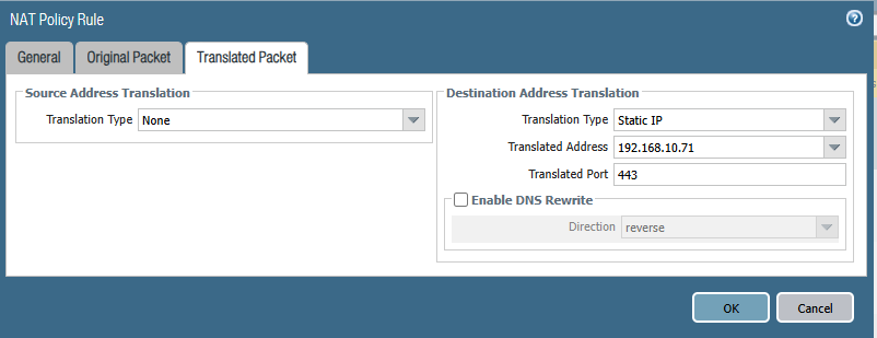
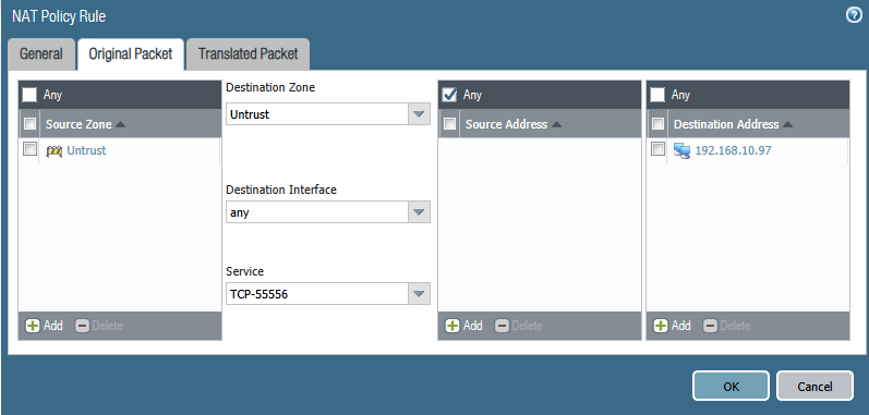
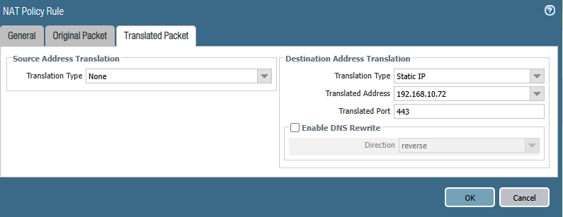
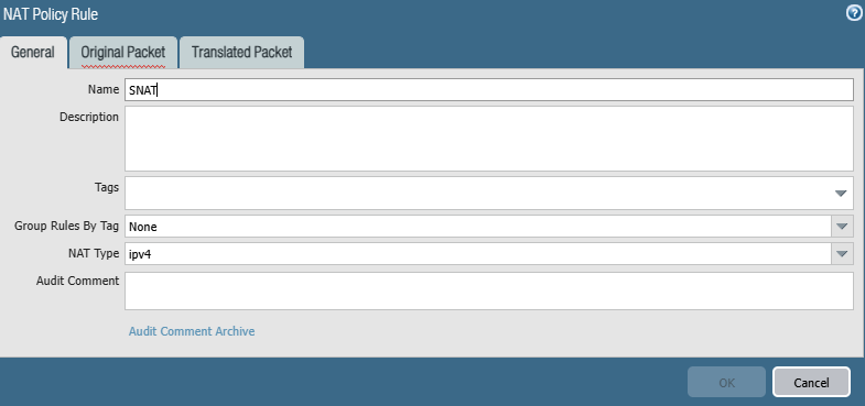
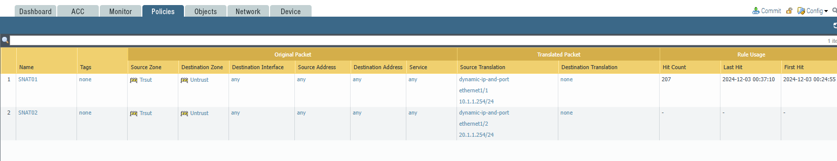
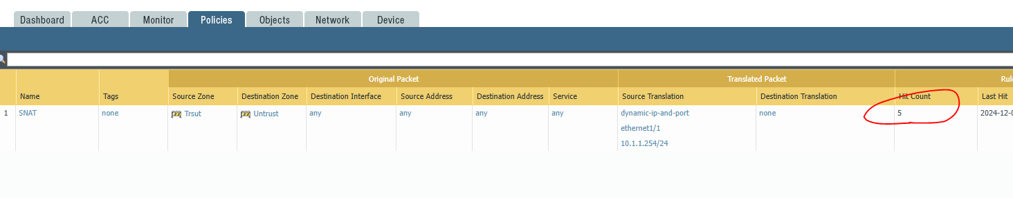
5. NAT를 설정합니다.
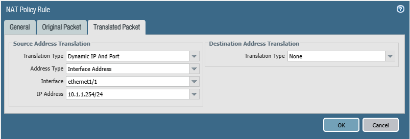
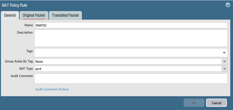
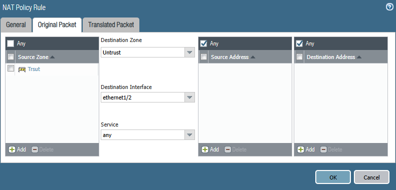
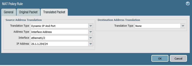
6. 이번에는 SNAT02를 만듭니다.
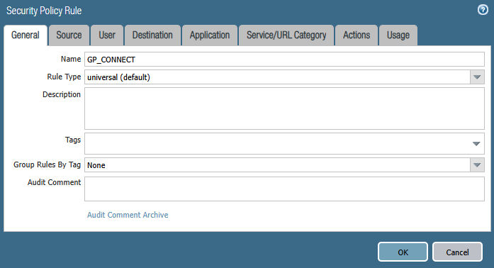
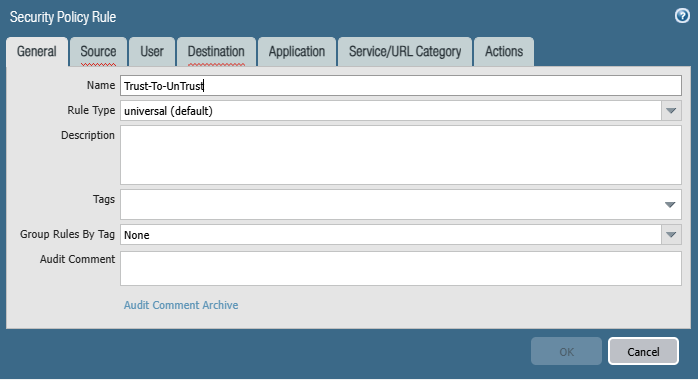
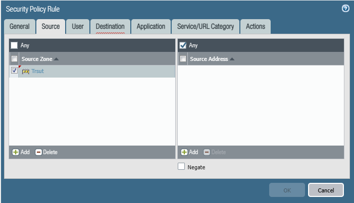
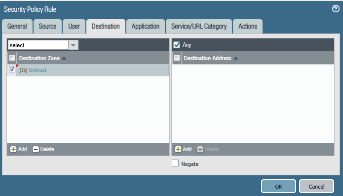
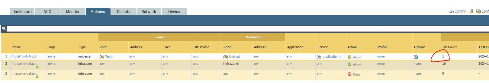
7. Policy를 설정합니다
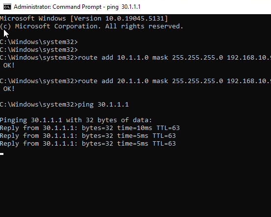
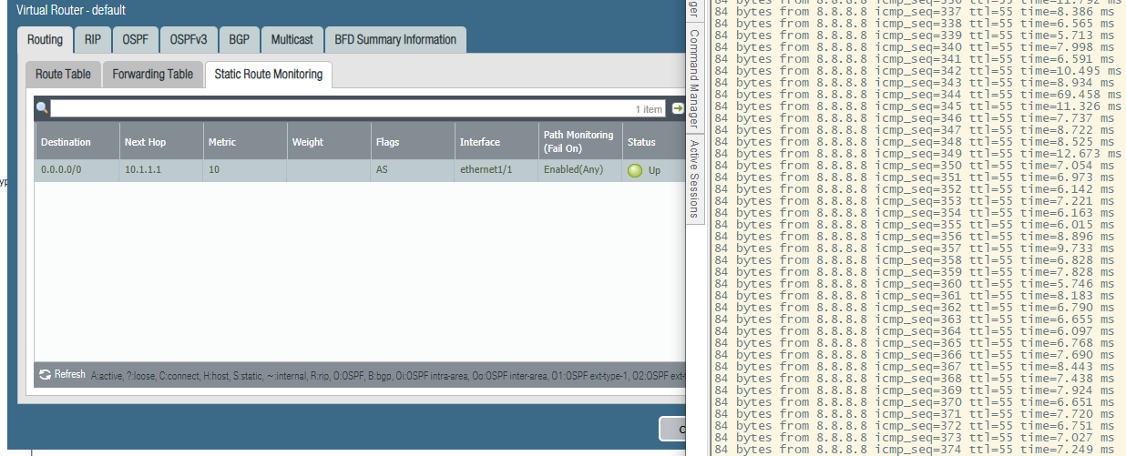
7. VPC 에서 Ping 8.8.8.8 시도 합니다.
VPCS> ping 8.8.8.8
84 bytes from 8.8.8.8 icmp_seq=1 ttl=55 time=30.465 ms 84 bytes from 8.8.8.8 icmp_seq=2 ttl=55 time=6.784 ms 84 bytes from 8.8.8.8 icmp_seq=3 ttl=55 time=7.433 ms 84 bytes from 8.8.8.8 icmp_seq=4 ttl=55 time=6.824 ms 84 bytes from 8.8.8.8 icmp_seq=5 ttl=55 time=6.570 ms
84 bytes from 30.1.1.254 icmp_seq=1 ttl=64 time=18.113 ms 84 bytes from 30.1.1.254 icmp_seq=2 ttl=64 time=2.498 ms 84 bytes from 30.1.1.254 icmp_seq=3 ttl=64 time=2.753 ms 84 bytes from 30.1.1.254 icmp_seq=4 ttl=64 time=2.241 ms 84 bytes from 30.1.1.254 icmp_seq=5 ttl=64 time=3.220 ms
VPCS>
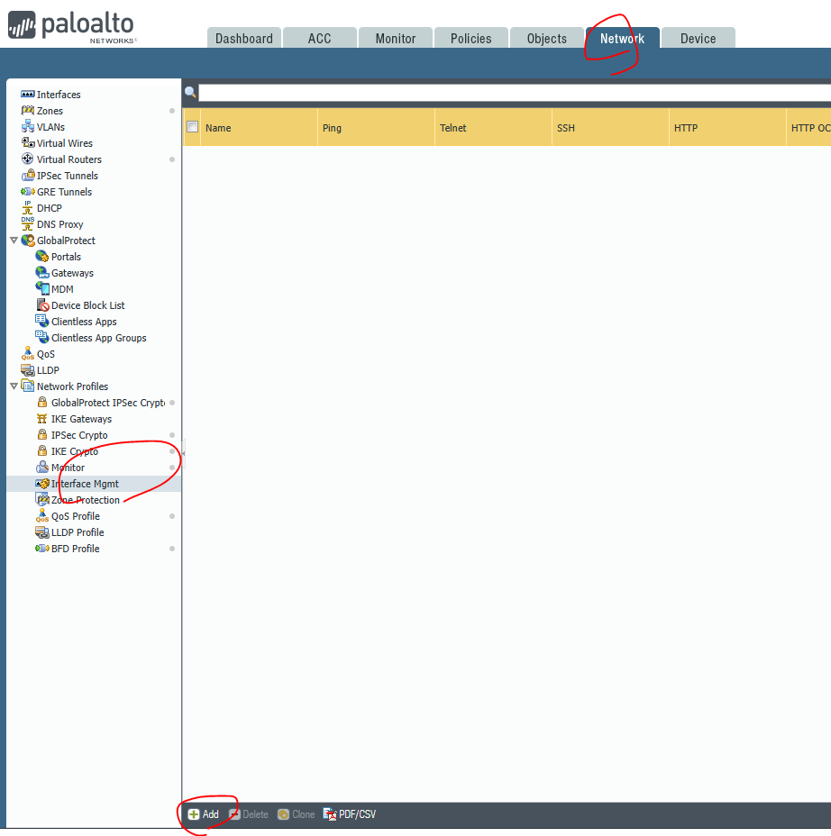
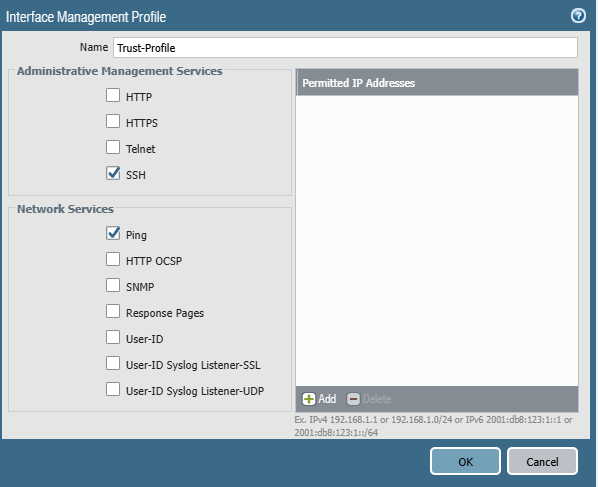
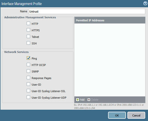
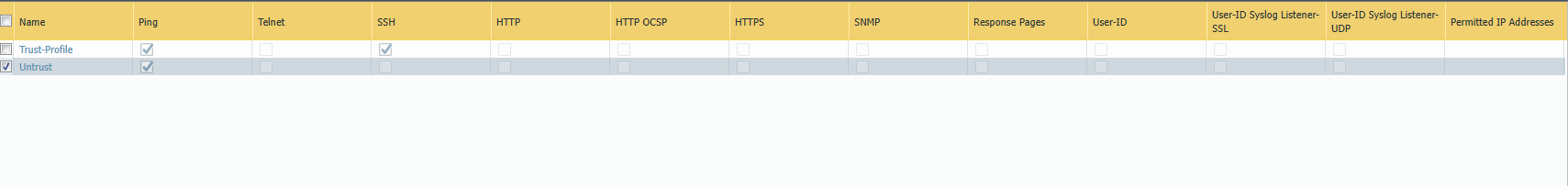
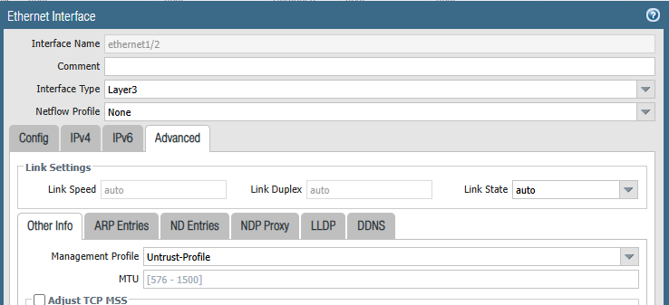
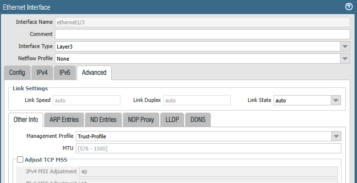
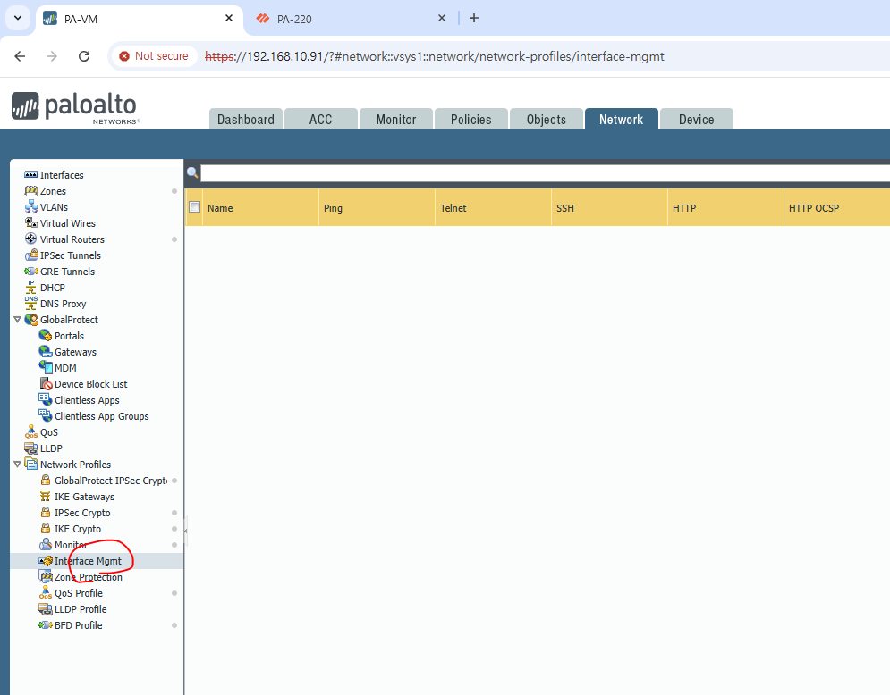
지금까지 PaloAlto Interface Mgmt Profile에 대해서 알아보았습니다.
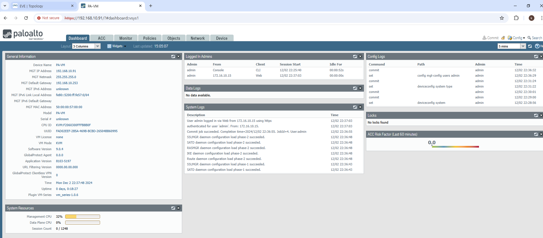
------------------------------------------------------------------------------- Name: Management Interface Link status: Runtime link speed/duplex/state: 1000/full/up Configured link speed/duplex/state: auto/auto/auto MAC address: Port MAC address 50:00:00:57:00:00
Ip address: 192.168.10.91 Netmask: 255.255.255.0 Default gateway: 192.168.10.253 Ipv6 address: unknown Ipv6 link local address: fe80::5200:ff:fe57:0/64 Ipv6 default gateway: -------------------------------------------------------------------------------
VLAN Name Status Ports ---- -------------------------------- --------- ------------------------------- 1 default active Gi1/0/1, Gi1/0/2, Gi1/0/3 Gi1/0/4, Gi1/0/5, Gi1/0/6 Gi1/0/7, Gi1/0/8, Gi1/0/9 Gi1/0/10, Gi1/0/11, Gi1/0/12 Gi1/0/13, Gi1/0/14, Gi1/0/15 Gi1/0/16, Gi1/0/17, Gi1/0/18 Gi1/0/19, Gi1/0/20, Gi1/0/21 Gi1/0/22, Gi1/0/23, Gi1/0/24 Te1/1/1, Te1/1/2, Te1/1/3 Te1/1/4 4 VLAN0004 active 10 VLAN0010 active 20 VLAN0020 active
Switch#show ip int brie Interface IP-Address OK? Method Status Protocol Vlan1 unassigned YES NVRAM down down Vlan10 10.10.10.253 YES manual down down Vlan20 20.20.20.253 YES manual down down
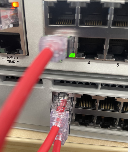
4. 케이블 연결
5. LACP 확인
Switch#show etherchannel summary Flags: D - down P - bundled in port-channel I - stand-alone s - suspended H - Hot-standby (LACP only) R - Layer3 S - Layer2 U - in use f - failed to allocate aggregator
M - not in use, minimum links not met u - unsuitable for bundling w - waiting to be aggregated d - default port
A - formed by Auto LAG
Number of channel-groups in use: 1 Number of aggregators: 1
Group Port-channel Protocol Ports ------+-------------+-----------+----------------------------------------------- 1 Po1(SU) LACP Gi1/0/1(P) Gi1/0/2(P)
Switch#
6. Ping 테스트
Switch#ping 10.10.10.254 source vlan 10 Type escape sequence to abort. Sending 5, 100-byte ICMP Echos to 10.10.10.254, timeout is 2 seconds: Packet sent with a source address of 10.10.10.253 .!!!! Success rate is 80 percent (4/5), round-trip min/avg/max = 1/1/4 ms Switch#ping 20.20.20.254 sou Switch#ping 20.20.20.254 source vlan 20 Type escape sequence to abort. Sending 5, 100-byte ICMP Echos to 20.20.20.254, timeout is 2 seconds: Packet sent with a source address of 20.20.20.253 .!!!! Success rate is 80 percent (4/5), round-trip min/avg/max = 1/1/4 ms Switch#
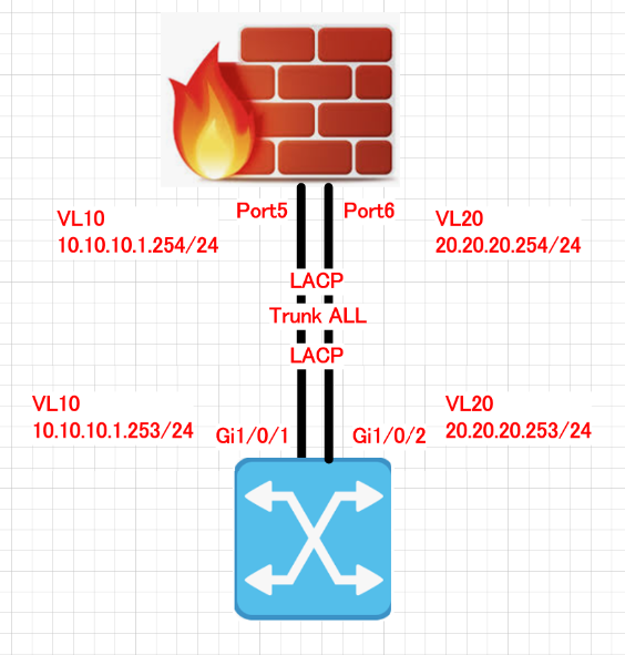
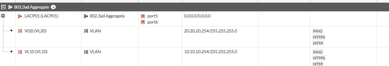
지금까지 fortigate인터페이스를 LACP설정하고 VLAN10 and VLAN20 interface 만들어서 Cisco Switch랑 통신 하는 방법에 대해서 알아보았습니다.
VLAN Name Status Ports ---- -------------------------------- --------- ------------------------------- 1 default active Gi1/0/2, Gi1/0/3, Gi1/0/4 Gi1/0/5, Gi1/0/6, Gi1/0/7 Gi1/0/8, Gi1/0/9, Gi1/0/10 Gi1/0/11, Gi1/0/12, Gi1/0/13 Gi1/0/14, Gi1/0/15, Gi1/0/16 Gi1/0/17, Gi1/0/18, Gi1/0/19 Gi1/0/20, Gi1/0/21, Gi1/0/22 Gi1/0/23, Gi1/0/24, Te1/1/1 Te1/1/2, Te1/1/3, Te1/1/4 4 VLAN0004 active 10 VLAN0010 active 20 VLAN0020 active 70 VLAN0070 active 71 VLAN0071 active 72 VLAN0072 active 73 VLAN0073 active 1002 fddi-default act/unsup 1003 token-ring-default act/unsup 1004 fddinet-default act/unsup 1005 trnet-default act/unsup Switch#show ip int brie Interface IP-Address OK? Method Status Protocol Vlan1 unassigned YES NVRAM up up Vlan10 10.10.10.253 YES manual up up Vlan20 20.20.20.253 YES manual up up
5. Ping테스트
Switch#ping 10.10.10.254 source vlan 10 Type escape sequence to abort. Sending 5, 100-byte ICMP Echos to 10.10.10.254, timeout is 2 seconds: Packet sent with a source address of 10.10.10.253 .!!!! Success rate is 80 percent (4/5), round-trip min/avg/max = 1/1/1 ms Switch#ping 20.20.20.254 source vlan 20 Type escape sequence to abort. Sending 5, 100-byte ICMP Echos to 20.20.20.254, timeout is 2 seconds: Packet sent with a source address of 20.20.20.253 .!!!! Success rate is 80 percent (4/5), round-trip min/avg/max = 1/1/1 ms
지금까지 방화벽 Port6에 VLAN interface를 생성해서 동작하는 방법에 대해서 알아보았습니다.
기본 설정은 위에 글을 참고 부탁드립니다. 이번 글에서 STP 설정에 대해서만 다루겠습니다.
1. Switch에서 G1/0/1 and G1/0/2를 Trunk를 설정 합니다.
interface GigabitEthernet1/0/1 switchport mode trunk end
Switch#show run int g1/0/2 Building configuration...
Current configuration : 61 bytes ! interface GigabitEthernet1/0/2 switchport mode trunk end
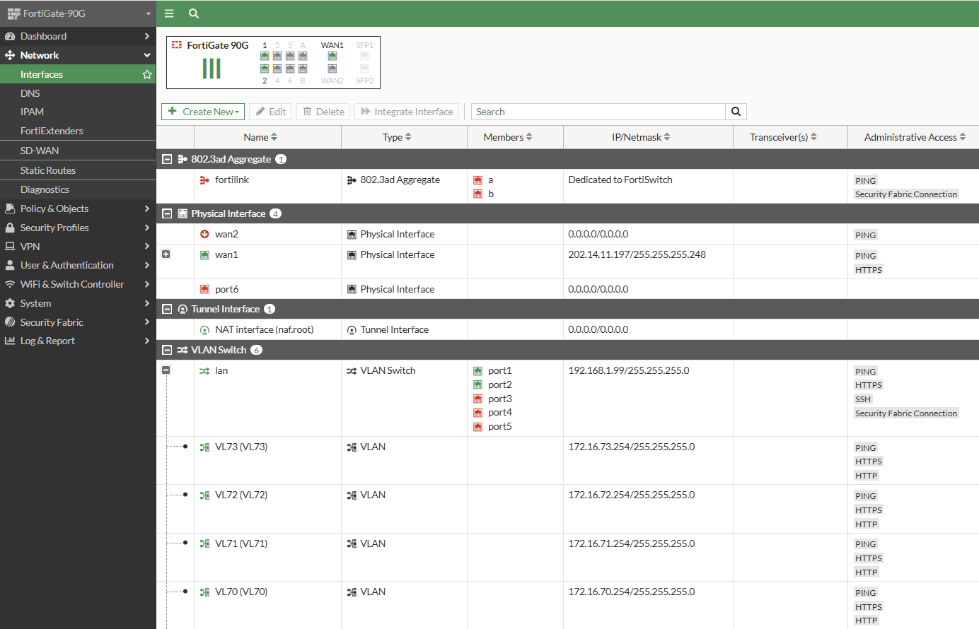
2. Fortigate에서 stp설정을 확인 합니다.
디폴트롤 STP enable입니다.
FortiGate-90G # config system interface
FortiGate-90G (interface) # edit lan
FortiGate-90G (lan) # show config system interface edit "lan" set vdom "root" set ip 192.168.1.99 255.255.255.0 set allowaccess ping https ssh fabric set type hard-switch set stp enable set role lan set snmp-index 15 next end
FortiGate-90G (lan) #
3. Switch에서 STP를 확인 합니다.
디폴트로 STP enable 입니다. 그리고 G1/0/2가 Blocking Port입니다.
Switch#show spanning-tree vlan 70
VLAN0070 Spanning tree enabled protocol rstp Root ID Priority 32838 Address 084f.a946.6900 This bridge is the root Hello Time 2 sec Max Age 20 sec Forward Delay 15 sec
Bridge ID Priority 32838 (priority 32768 sys-id-ext 70) Address 084f.a946.6900 Hello Time 2 sec Max Age 20 sec Forward Delay 15 sec Aging Time 300 sec
Interface Role Sts Cost Prio.Nbr Type ------------------- ---- --- --------- -------- -------------------------------- Gi1/0/1 Desg FWD 4 128.1 P2p Gi1/0/2 Back BLK 4 128.2 P2p
Switch#show spanning-tree vlan 71
VLAN0071 Spanning tree enabled protocol rstp Root ID Priority 32839 Address 084f.a946.6900 This bridge is the root Hello Time 2 sec Max Age 20 sec Forward Delay 15 sec
Bridge ID Priority 32839 (priority 32768 sys-id-ext 71) Address 084f.a946.6900 Hello Time 2 sec Max Age 20 sec Forward Delay 15 sec Aging Time 300 sec
Interface Role Sts Cost Prio.Nbr Type ------------------- ---- --- --------- -------- -------------------------------- Gi1/0/1 Desg FWD 4 128.1 P2p Gi1/0/2 Back BLK 4 128.2 P2p
Switch#show spanning-tree vlan 72
VLAN0072 Spanning tree enabled protocol rstp Root ID Priority 32840 Address 084f.a946.6900 This bridge is the root Hello Time 2 sec Max Age 20 sec Forward Delay 15 sec
Bridge ID Priority 32840 (priority 32768 sys-id-ext 72) Address 084f.a946.6900 Hello Time 2 sec Max Age 20 sec Forward Delay 15 sec Aging Time 300 sec
Interface Role Sts Cost Prio.Nbr Type ------------------- ---- --- --------- -------- -------------------------------- Gi1/0/1 Desg FWD 4 128.1 P2p Gi1/0/2 Back BLK 4 128.2 P2p
Switch#show spanning-tree vlan 73
VLAN0073 Spanning tree enabled protocol rstp Root ID Priority 32841 Address 084f.a946.6900 This bridge is the root Hello Time 2 sec Max Age 20 sec Forward Delay 15 sec
Bridge ID Priority 32841 (priority 32768 sys-id-ext 73) Address 084f.a946.6900 Hello Time 2 sec Max Age 20 sec Forward Delay 15 sec Aging Time 300 sec
Interface Role Sts Cost Prio.Nbr Type ------------------- ---- --- --------- -------- -------------------------------- Gi1/0/1 Desg FWD 4 128.1 P2p Gi1/0/2 Back BLK 4 128.2 P2p
Switch#
Switch#show run | in span spanning-tree mode rapid-pvst spanning-tree extend system-id
4. Ping테스트를 해보겠습니다.
정상적으로 동작 합니다.
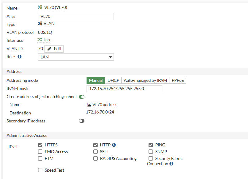
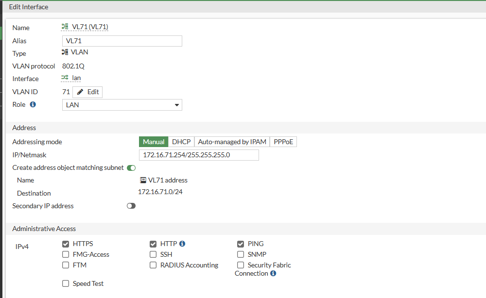
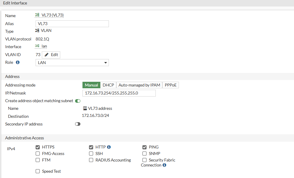
Switch#ping 172.16.70.254 source vlan 70 Type escape sequence to abort. Sending 5, 100-byte ICMP Echos to 172.16.70.254, timeout is 2 seconds: Packet sent with a source address of 172.16.70.253 .!!!! Success rate is 80 percent (4/5), round-trip min/avg/max = 1/1/1 ms Switch#ping 172.16.71.254 source vlan 71 Type escape sequence to abort. Sending 5, 100-byte ICMP Echos to 172.16.71.254, timeout is 2 seconds: Packet sent with a source address of 172.16.71.253 .!!!! Success rate is 80 percent (4/5), round-trip min/avg/max = 1/1/4 ms Switch#ping 172.16.72.254 source vlan 72 Type escape sequence to abort. Sending 5, 100-byte ICMP Echos to 172.16.72.254, timeout is 2 seconds: Packet sent with a source address of 172.16.72.253 .!!!! Success rate is 80 percent (4/5), round-trip min/avg/max = 1/1/4 ms Switch#ping 172.16.73.254 source vlan 73 Type escape sequence to abort. Sending 5, 100-byte ICMP Echos to 172.16.73.254, timeout is 2 seconds: Packet sent with a source address of 172.16.73.253 .!!!! Success rate is 80 percent (4/5), round-trip min/avg/max = 1/1/1 ms Switch#
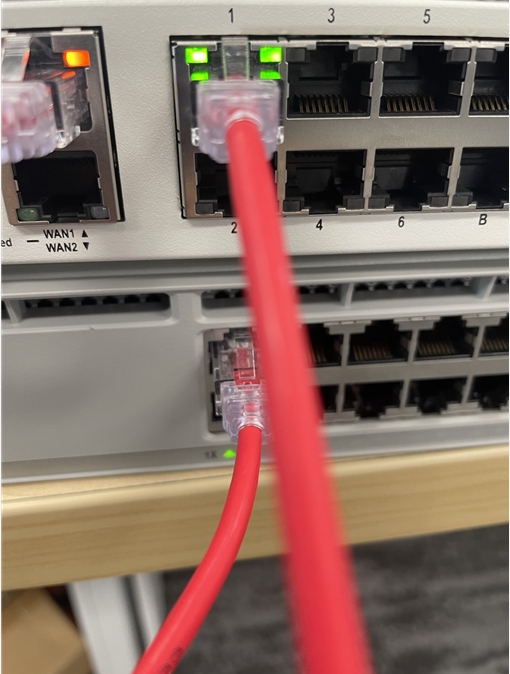
5. 포티넷 방화벽에서 port1 케이블을 제거 합니다.
6. Switch에서 STP상태를 확인 합니다.
Switch#show spanning-tree vlan 70
VLAN0070 Spanning tree enabled protocol rstp Root ID Priority 32838 Address 084f.a946.6900 This bridge is the root Hello Time 2 sec Max Age 20 sec Forward Delay 15 sec
Bridge ID Priority 32838 (priority 32768 sys-id-ext 70) Address 084f.a946.6900 Hello Time 2 sec Max Age 20 sec Forward Delay 15 sec Aging Time 300 sec
Interface Role Sts Cost Prio.Nbr Type ------------------- ---- --- --------- -------- -------------------------------- Gi1/0/2 Desg FWD 4 128.2 P2p
Switch#show spanning-tree vlan 71
VLAN0071 Spanning tree enabled protocol rstp Root ID Priority 32839 Address 084f.a946.6900 This bridge is the root Hello Time 2 sec Max Age 20 sec Forward Delay 15 sec
Bridge ID Priority 32839 (priority 32768 sys-id-ext 71) Address 084f.a946.6900 Hello Time 2 sec Max Age 20 sec Forward Delay 15 sec Aging Time 300 sec
Interface Role Sts Cost Prio.Nbr Type ------------------- ---- --- --------- -------- -------------------------------- Gi1/0/2 Desg FWD 4 128.2 P2p
Switch#show spanning-tree vlan 72
VLAN0072 Spanning tree enabled protocol rstp Root ID Priority 32840 Address 084f.a946.6900 This bridge is the root Hello Time 2 sec Max Age 20 sec Forward Delay 15 sec
Bridge ID Priority 32840 (priority 32768 sys-id-ext 72) Address 084f.a946.6900 Hello Time 2 sec Max Age 20 sec Forward Delay 15 sec Aging Time 300 sec
Interface Role Sts Cost Prio.Nbr Type ------------------- ---- --- --------- -------- -------------------------------- Gi1/0/2 Desg FWD 4 128.2 P2p
Switch#show spanning-tree vlan 73
VLAN0073 Spanning tree enabled protocol rstp Root ID Priority 32841 Address 084f.a946.6900 This bridge is the root Hello Time 2 sec Max Age 20 sec Forward Delay 15 sec
Bridge ID Priority 32841 (priority 32768 sys-id-ext 73) Address 084f.a946.6900 Hello Time 2 sec Max Age 20 sec Forward Delay 15 sec Aging Time 300 sec
Interface Role Sts Cost Prio.Nbr Type ------------------- ---- --- --------- -------- -------------------------------- Gi1/0/2 Desg FWD 4 128.2 P2p
Switch#
7. Ping 테스트를 합니다.
Switch#ping 172.16.70.254 source vlan 70 Type escape sequence to abort. Sending 5, 100-byte ICMP Echos to 172.16.70.254, timeout is 2 seconds: Packet sent with a source address of 172.16.70.253 .!!!! Success rate is 80 percent (4/5), round-trip min/avg/max = 1/1/4 ms Switch#ping 172.16.71.254 source vlan 71 Type escape sequence to abort. Sending 5, 100-byte ICMP Echos to 172.16.71.254, timeout is 2 seconds: Packet sent with a source address of 172.16.71.253 .!!!! Success rate is 80 percent (4/5), round-trip min/avg/max = 1/1/4 ms Switch#ping 172.16.72.254 source vlan 72 Type escape sequence to abort. Sending 5, 100-byte ICMP Echos to 172.16.72.254, timeout is 2 seconds: Packet sent with a source address of 172.16.72.253 .!!!! Success rate is 80 percent (4/5), round-trip min/avg/max = 1/1/1 ms Switch#ping 172.16.73.254 source vlan 73 Type escape sequence to abort. Sending 5, 100-byte ICMP Echos to 172.16.73.254, timeout is 2 seconds: Packet sent with a source address of 172.16.73.253 .!!!! Success rate is 80 percent (4/5), round-trip min/avg/max = 1/1/1 ms Switch#
Switch(config)#int vlan 70 Switch(config-if)#ip add 172.16.70.253 255.255.255.0 Switch(config-if)#no sh Switch(config-if)#int vlan 71 Switch(config-if)#ip add 172.16.71.253 255.255.255.0 Switch(config-if)#no sh Switch(config-if)#int vlan 72 Switch(config-if)#ip add 172.16.72.253 255.255.255.0 Switch(config-if)#no sh Switch(config-if)#int vlan 73 Switch(config-if)#ip add 172.16.73.253 255.255.255.0 Switch(config-if)#no sh Switch(config-if)# Switch(config-if)#end
2. 케이블을 연결 합니다.
Fortigate port1 <---> port 1/0/1 SW
3. SW설정값을 확인 합니다.
Switch#show vlan brie
VLAN Name Status Ports ---- -------------------------------- --------- ------------------------------- 1 default active Gi1/0/2, Gi1/0/3, Gi1/0/4 Gi1/0/5, Gi1/0/6, Gi1/0/7 Gi1/0/8, Gi1/0/9, Gi1/0/10 Gi1/0/11, Gi1/0/12, Gi1/0/13 Gi1/0/14, Gi1/0/15, Gi1/0/16 Gi1/0/17, Gi1/0/18, Gi1/0/19 Gi1/0/20, Gi1/0/21, Gi1/0/22 Gi1/0/23, Gi1/0/24, Te1/1/1 Te1/1/2, Te1/1/3, Te1/1/4 4 VLAN0004 active 70 VLAN0070 active 71 VLAN0071 active 72 VLAN0072 active 73 VLAN0073 active 1002 fddi-default act/unsup 1003 token-ring-default act/unsup 1004 fddinet-default act/unsup 1005 trnet-default act/unsup Switch#
Switch#show ip int brie Interface IP-Address OK? Method Status Protocol Vlan1 unassigned YES NVRAM up up Vlan70 172.16.70.253 YES manual up up Vlan71 172.16.71.253 YES manual up up Vlan72 172.16.72.253 YES manual up up Vlan73 172.16.73.253 YES manual up up
4. 스위치에서 방화벽쪽으로 PING를 테스트 합니다.
Switch#ping 172.16.70.254 source vlan 70 Type escape sequence to abort. Sending 5, 100-byte ICMP Echos to 172.16.70.254, timeout is 2 seconds: Packet sent with a source address of 172.16.70.253 .!!!! Success rate is 80 percent (4/5), round-trip min/avg/max = 1/1/4 ms Switch#ping 172.16.71.254 source vlan 71 Type escape sequence to abort. Sending 5, 100-byte ICMP Echos to 172.16.71.254, timeout is 2 seconds: Packet sent with a source address of 172.16.71.253 .!!!! Success rate is 80 percent (4/5), round-trip min/avg/max = 1/1/4 ms Switch#ping 172.16.72.254 source vlan 72 Type escape sequence to abort. Sending 5, 100-byte ICMP Echos to 172.16.72.254, timeout is 2 seconds: Packet sent with a source address of 172.16.72.253 .!!!! Success rate is 80 percent (4/5), round-trip min/avg/max = 1/1/1 ms Switch#ping 172.16.73.254 source vlan 73 Type escape sequence to abort. Sending 5, 100-byte ICMP Echos to 172.16.73.254, timeout is 2 seconds: Packet sent with a source address of 172.16.73.253 .!!!! Success rate is 80 percent (4/5), round-trip min/avg/max = 1/1/1 ms Switch#
이번에는 포트를 변경해보겠습니다.
Fortigate port2 <-------> port1/0/1 SW
다시 Ping를 테스트 합니다.
Switch#ping 172.16.70.254 source vlan 70 Type escape sequence to abort. Sending 5, 100-byte ICMP Echos to 172.16.70.254, timeout is 2 seconds: Packet sent with a source address of 172.16.70.253 .!!!! Success rate is 80 percent (4/5), round-trip min/avg/max = 1/1/4 ms Switch#ping 172.16.71.254 source vlan 71 Type escape sequence to abort. Sending 5, 100-byte ICMP Echos to 172.16.71.254, timeout is 2 seconds: Packet sent with a source address of 172.16.71.253 .!!!! Success rate is 80 percent (4/5), round-trip min/avg/max = 1/1/4 ms Switch#ping 172.16.72.254 source vlan 72 Type escape sequence to abort. Sending 5, 100-byte ICMP Echos to 172.16.72.254, timeout is 2 seconds: Packet sent with a source address of 172.16.72.253 .!!!! Success rate is 80 percent (4/5), round-trip min/avg/max = 1/1/1 ms Switch#ping 172.16.73.254 source vlan 73 Type escape sequence to abort. Sending 5, 100-byte ICMP Echos to 172.16.73.254, timeout is 2 seconds: Packet sent with a source address of 172.16.73.253 .!!!! Success rate is 80 percent (4/5), round-trip min/avg/max = 1/1/1 ms Switch#
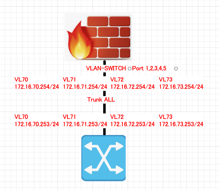
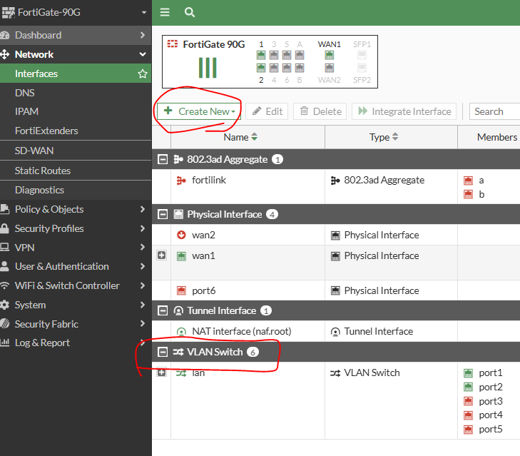
VLAN-SWITCH에 포함된 PORT들은 아무 포트나 연결하면 VLAN 70 - IP, VLAN 71 - IP, VLAN 72 - IP, VLAN73 -IP랑 통신 가능 합니다.
VLAN-SWITCH<---> HARD-SWITCH랑 같습니다.
edit "lan" set vdom "root" set ip 192.168.1.99 255.255.255.0 set allowaccess ping https ssh fabric set type hard-switch set stp enable set role lan set snmp-index 15
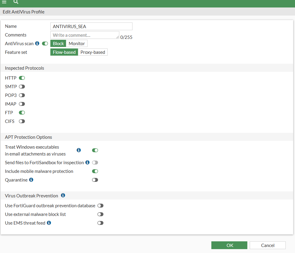
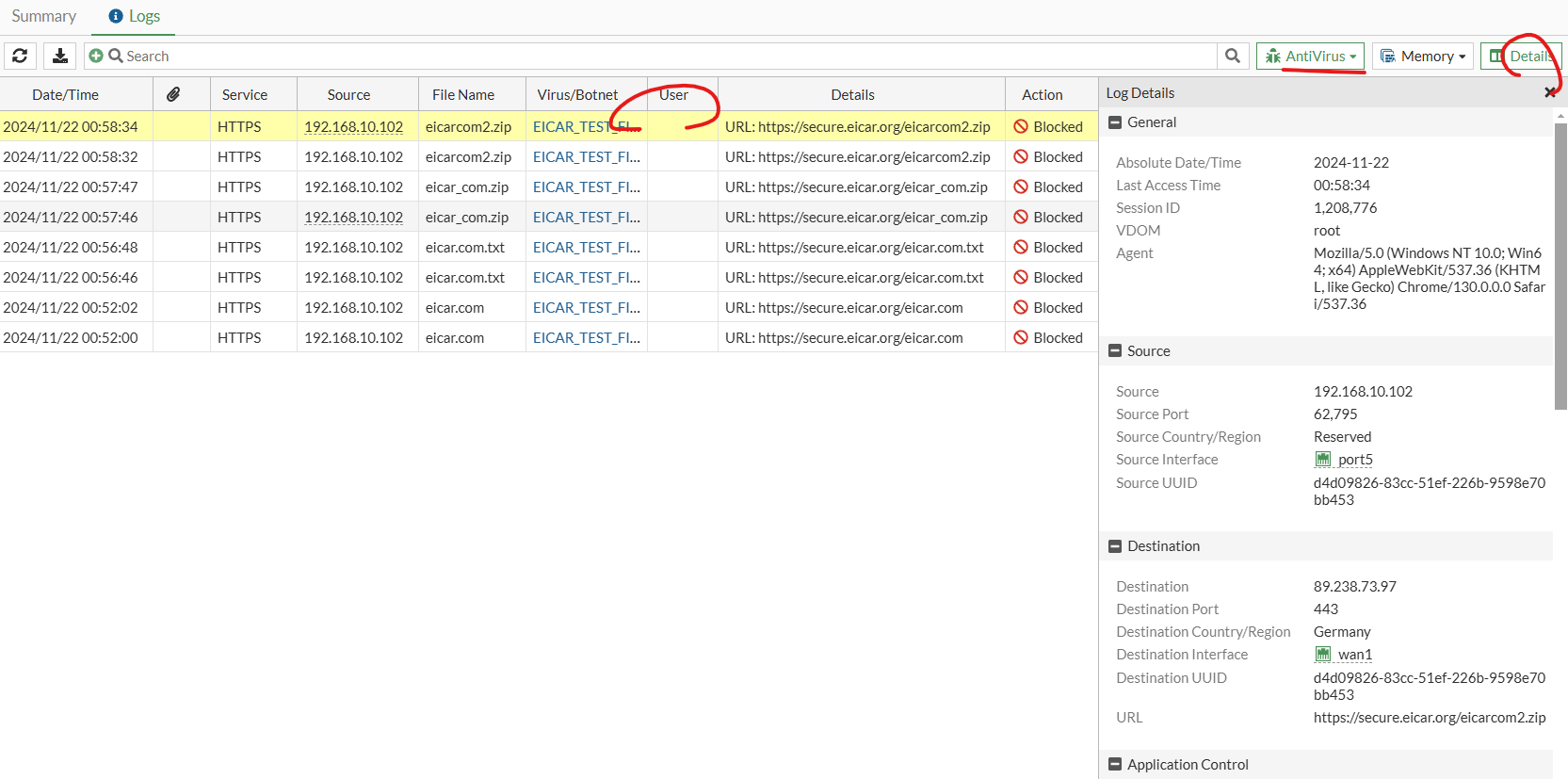
Activirus Profile은 FortiGate에 In/out Traffic를 inspect해서 Viruses, Worms, and Trojans & Spyware download 등을 검사하고 방화벽 내부를 보호 합니다.
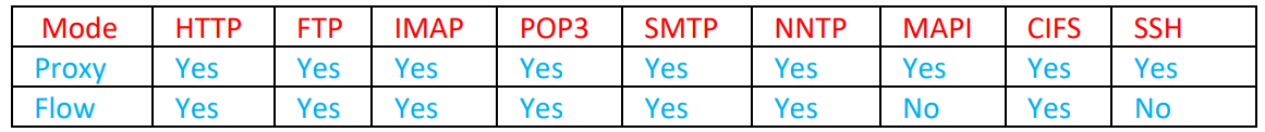
모든 프로토콜이 다 지원되는것은 아니고 HTTP, FTP, IMAP, POP3, SMTP, CIFS 및 NNTP 세션에 바이러스 백신 보호를 적용하도록 구성할 수 있고. 프록시 기반 프로필은 MAPI 및 SSH도 지원합니다. 바이러스 백신 검사는 잠재적으로 원하지 않는 악성 파일이 네트워크에 유입되는 것을 방지합니다. 바이러스 백신 프로필에는 파일의 바이러스 서명 검색, 지능형 지속 위협 검색, 외부 맬웨어 해시 목록 및 위협 피드 확인 등과 같은 다양한 기능이 포함되어 있습니다. 악성 파일을 차단하거나 모니터링하고 격리할 수 있습니다. 일부 바이러스 백신 프로필 옵션에는 라이선스 및/또는 기타 Fortinet 제품이 필요합니다. 일부 바이러스 백신 프로필 옵션은 CL에서만 구성할 수 있습니다.
Antivirus scan은 malware in executables, PDF files, and HTML, ㄴJavaScript viruses, inside compresessed files and data encoding schemes 포함 합니다.
Antivirus Profile은 Flow-based and Porxy-based antivirus를 모두 지원합니다.
하지만 flow base antivirus 방식이 더 좋은 performance를 제공합니다.
방식별로 지원되는 프로토콜 종류 입니다.
1. invirus Profile를 생성 하거나 디폴트 값을 사용 합니다.
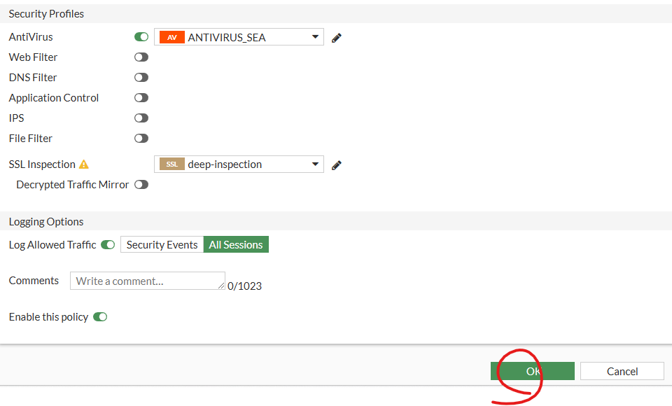
2. 인터넷으로 나가는 방화벽 정책을 만들고 AV profile를 선택 합니다.
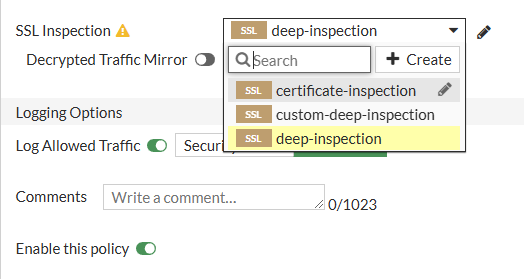
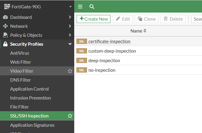
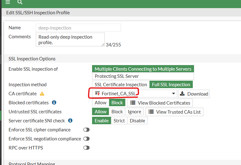
AntiVirus를 제대로 동작하기 위해서는 SSL Inspection -> mode가 deep-inspection이 필요합니다.
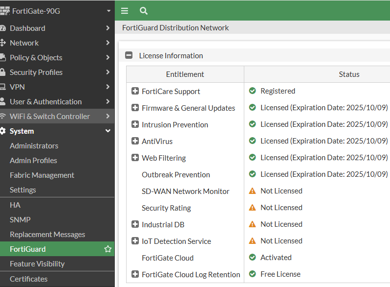
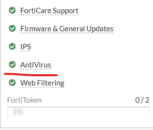
3. AntiVirus 라이센스가 있는지 꼭 확인 합니다.
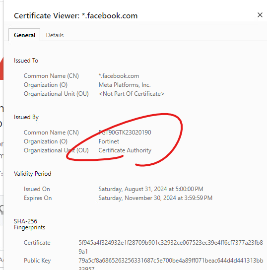
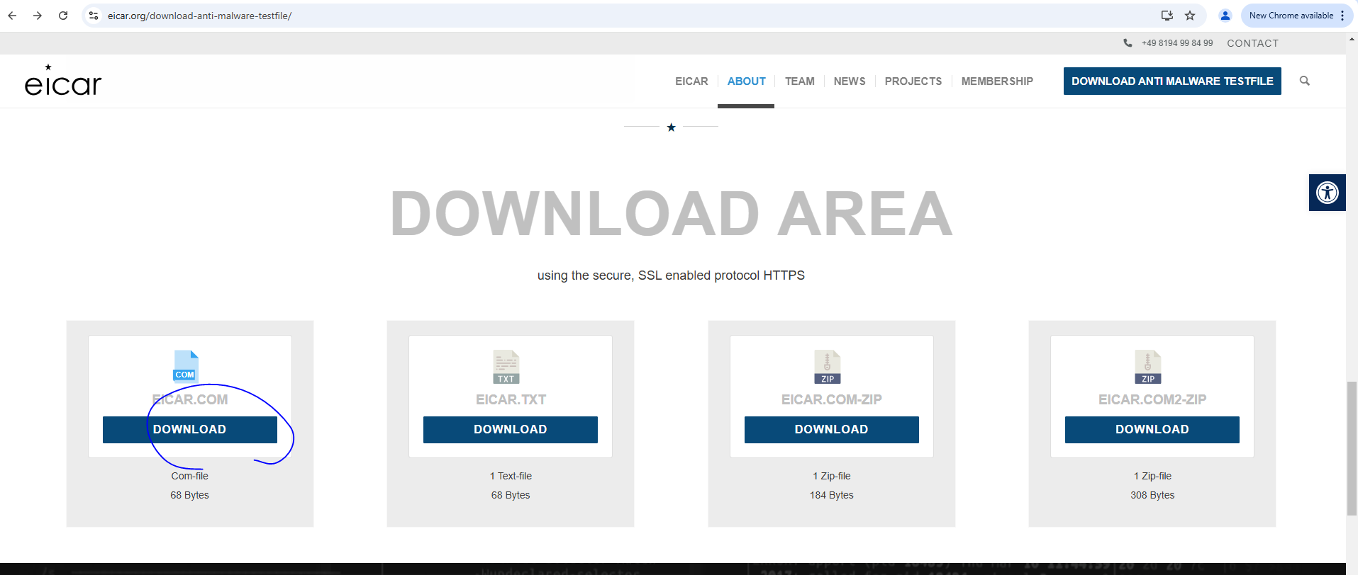
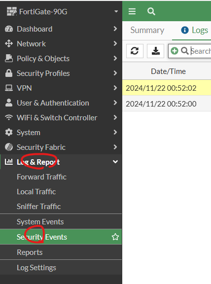
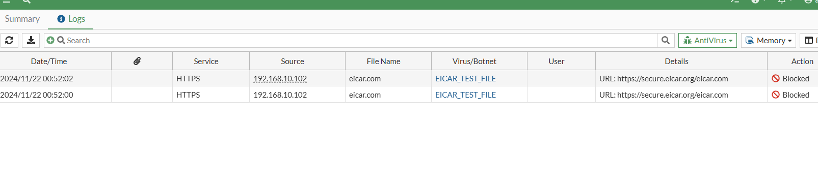
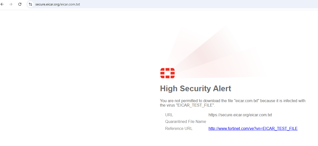
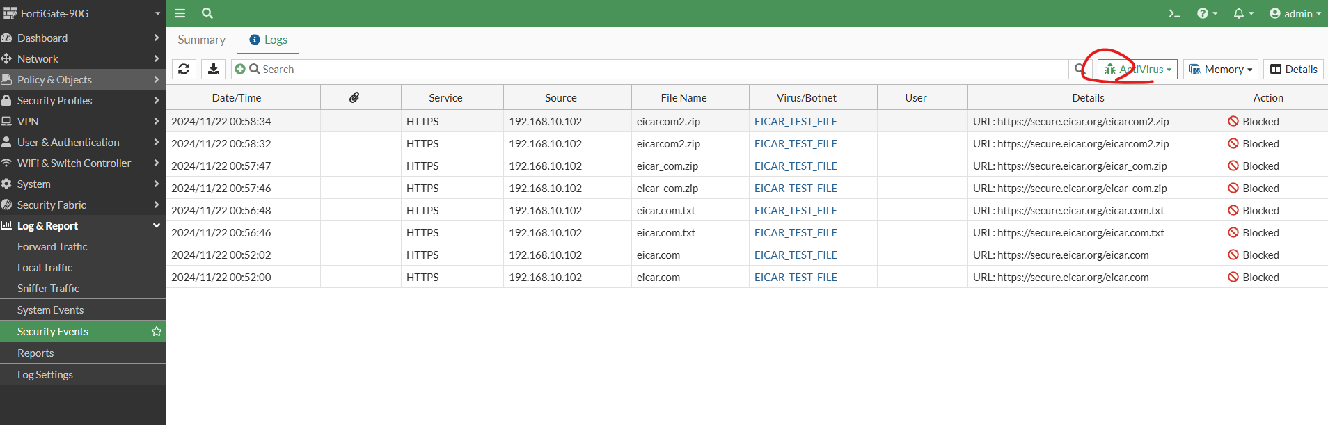
4. PC에서 바이러스를 다운로드 받아서 실제로 Fortigate 방화벽이 인지를 하는지 확인해보겠습니다.
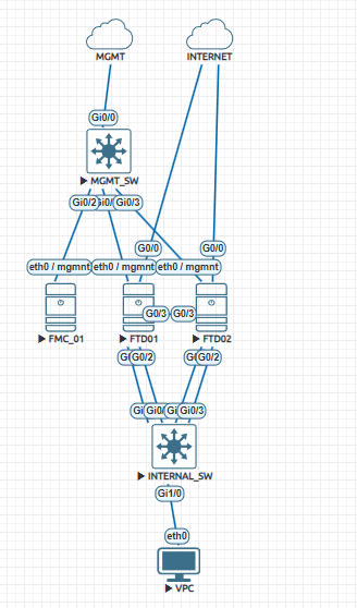
MGMT SW설정입니다. 현재 사용하시는 EVE-NG 구성도에 따라서 기본적인 설정값은 다를수 있습니다.
en conf t vlan 10 !\ interface GigabitEthernet0/1 switchport access vlan 10 switchport mode access ! interface GigabitEthernet0/2 switchport access vlan 10 switchport mode access ! interface GigabitEthernet0/3 switchport access vlan 10 switchport mode access ! interface GigabitEthernet0/0 no switchport ip address 192.168.10.233 255.255.255.0 negotiation auto !nterface Vlan10 ip address 10.20.20.254 255.255.255.0 ! ip route 0.0.0.0 0.0.0.0 192.168.10.253 !
Vlan Check
MGMT_SW#show vlan brie
VLAN Name Status Ports ---- -------------------------------- --------- ------------------------------- 1 default active Gi1/0, Gi1/1, Gi1/2, Gi1/3 10 VLAN0010 active Gi0/1, Gi0/2, Gi0/3 1002 fddi-default act/unsup 1003 token-ring-default act/unsup 1004 fddinet-default act/unsup 1005 trnet-default act/unsup MGMT_SW#
Interface Status check
MGMT_SW#show ip int brie Interface IP-Address OK? Method Status Protocol GigabitEthernet0/1 unassigned YES unset up up GigabitEthernet0/2 unassigned YES unset up up GigabitEthernet0/3 unassigned YES unset up up GigabitEthernet0/0 192.168.10.233 YES NVRAM up up GigabitEthernet1/0 unassigned YES unset up up GigabitEthernet1/1 unassigned YES unset up up GigabitEthernet1/2 unassigned YES unset up up GigabitEthernet1/3 unassigned YES unset up up Vlan10 10.20.20.254 YES NVRAM up up MGMT_SW#
Routing Table check
MGMT_SW#show ip route Codes: L - local, C - connected, S - static, R - RIP, M - mobile, B - BGP D - EIGRP, EX - EIGRP external, O - OSPF, IA - OSPF inter area N1 - OSPF NSSA external type 1, N2 - OSPF NSSA external type 2 E1 - OSPF external type 1, E2 - OSPF external type 2 i - IS-IS, su - IS-IS summary, L1 - IS-IS level-1, L2 - IS-IS level-2 ia - IS-IS inter area, * - candidate default, U - per-user static route o - ODR, P - periodic downloaded static route, H - NHRP, l - LISP a - application route + - replicated route, % - next hop override
Gateway of last resort is 192.168.10.253 to network 0.0.0.0
S* 0.0.0.0/0 [1/0] via 192.168.10.253 10.0.0.0/8 is variably subnetted, 2 subnets, 2 masks C 10.20.20.0/24 is directly connected, Vlan10 L 10.20.20.254/32 is directly connected, Vlan10 192.168.10.0/24 is variably subnetted, 2 subnets, 2 masks C 192.168.10.0/24 is directly connected, GigabitEthernet0/0 L 192.168.10.233/32 is directly connected, GigabitEthernet0/0 MGMT_SW#
Ping Test to Default Gateway
MGMT_SW# ping 192.168.10.253 Type escape sequence to abort. Sending 5, 100-byte ICMP Echos to 192.168.10.253, timeout is 2 seconds: !!!!! Success rate is 100 percent (5/5), round-trip min/avg/max = 1/3/7 ms MGMT_SW# MGMT_SW#