안녕하세요.
오늘은 DUAL WAN구조에서 DDNS설정해보겠습니다.
Fortigate VM에서 설정해보겠습니다.
Fortigate VM은 DDNS CLI만 지원 합니다.
테스트 하기전에 DUAL WAN구조에서 IP SLA 부분을 설정 합니다.
https://itblog-kr.tistory.com/124
[Fortigate-#19]- IP SLA
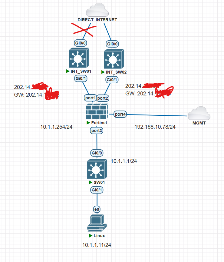
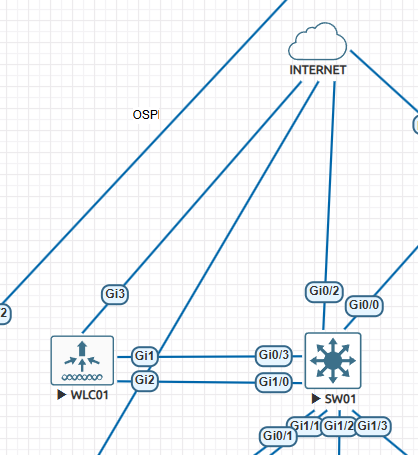
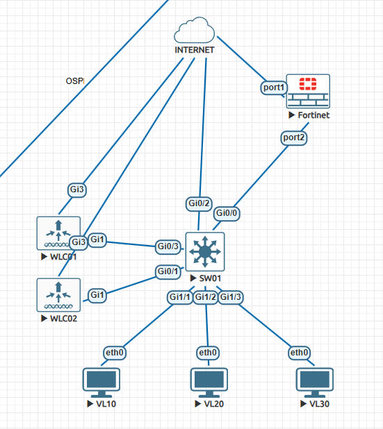
안녕하세요. 이번에는 Fortigate에서 IP SLA에 대해서 알아보겠습니다. 아래처럼 Fortigate입장에서 WAN 인터넷이 2개가 연결되어져 있고, AD값으로 WAN01이 MAIN internet WAN02가 BACKUP internet으로 동작중에
itblog-kr.tistory.com
현재 모든 TRAFFIC은 Default Gateway가 WAN01로 통신 합니다.
ISP01 - WAN01은 외부에 통신 가능
ISP02 - WAN02는 WAN01이 죽어야지 Default Gateway WAN02로 바뀌면서 통신 가능 합니다.
| config system ddns edit 1 set ddns-server FortiGuardDDNS set ddns-domain "fw1004.float-zone.com" set use-public-ip enable set update-interval 60 set monitor-interface "port1" "port2" |
디폴트 update-interval은 5분 입니다. 이 값은 1분으로 줄입니다.
| C:\Users\USER>ping fw1004.float-zone.com -t Ping fw1004.float-zone.com [202.X.X.196] 32바이트 데이터 사용: 202.X.X.196의 응답: 바이트=32 시간=17ms TTL=245 202. X.X .196의 응답: 바이트=32 시간=10ms TTL=245 202. X.X .196의 응답: 바이트=32 시간=13ms TTL=245 202. X.X .196의 응답: 바이트=32 시간=16ms TTL=245 202. X.X .196의 응답: 바이트=32 시간=25ms TTL=245 202. X.X .196에 대한 Ping 통계: 패킷: 보냄 = 5, 받음 = 5, 손실 = 0 (0% 손실), 왕복 시간(밀리초): 최소 = 10ms, 최대 = 25ms, 평균 = 16ms Control-C ^C C:\Users\USER> C:\Users\USER>nslookup fw1004.float-zone.com -t ^C C:\Users\USER>nslookup fw1004.float-zone.com 서버: UnKnown Address: 43.245.107.6 권한 없는 응답: 이름: fw1004.float-zone.com Address: 202. X.X .196 |
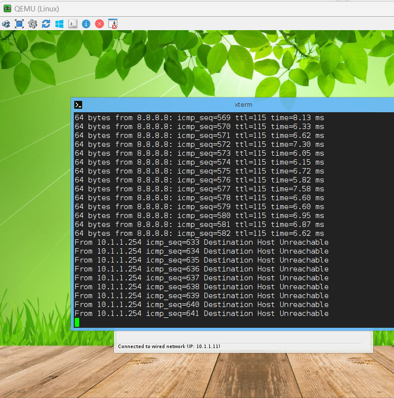
Fortigate에서 WAN01에서 케이블을 제거 합니다.
DDNS서버에 정보가 업데이트되고 ROOT DNS서버까지 동기화 하기 위해서는 조금 시간이 걸립니다.
5분 정도 기다립니다.
라우팅 테이블은 port2으로 ISP2으로 변경 되었습니다.
| fortiGate-VM64-KVM # get router info routing-table all Codes: K - kernel, C - connected, S - static, R - RIP, B - BGP O - OSPF, IA - OSPF inter area N1 - OSPF NSSA external type 1, N2 - OSPF NSSA external type 2 E1 - OSPF external type 1, E2 - OSPF external type 2 i - IS-IS, L1 - IS-IS level-1, L2 - IS-IS level-2, ia - IS-IS inter area * - candidate default Routing table for VRF=0 S* 0.0.0.0/0 [150/0] via 202. X.X .193, port2, [1/0] C 10.1.1.0/24 is directly connected, port3 |
| C:\Users\USER>ping fw1004.float-zone.com Ping fw1004.float-zone.com [202. X.X .197] 32바이트 데이터 사용: 202. X.X .197의 응답: 바이트=32 시간=18ms TTL=245 202. X.X .197의 응답: 바이트=32 시간=11ms TTL=245 202. X.X .197의 응답: 바이트=32 시간=9ms TTL=245 202. X.X .197의 응답: 바이트=32 시간=7ms TTL=245 202. X.X .197에 대한 Ping 통계: 패킷: 보냄 = 4, 받음 = 4, 손실 = 0 (0% 손실), 왕복 시간(밀리초): 최소 = 7ms, 최대 = 18ms, 평균 = 11ms C:\Users\USER> nslookup fw1004.float-zone.com 서버: UnKnown Address: 43.245.107.6 권한 없는 응답: 이름: fw1004.float-zone.com Address: 202.X.X.197 |
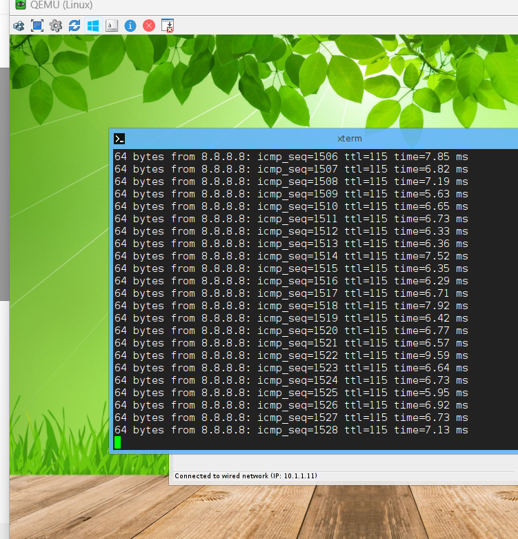
fortigate wan01 케이블을 다시 연결 합니다.
Default Gateway는 변경 되었습니다.
| FortiGate-VM64-KVM # get router info routing-table all Codes: K - kernel, C - connected, S - static, R - RIP, B - BGP O - OSPF, IA - OSPF inter area N1 - OSPF NSSA external type 1, N2 - OSPF NSSA external type 2 E1 - OSPF external type 1, E2 - OSPF external type 2 i - IS-IS, L1 - IS-IS level-1, L2 - IS-IS level-2, ia - IS-IS inter area * - candidate default Routing table for VRF=0 S* 0.0.0.0/0 [10/0] via 202. X.X .193, port1, [1/0] C 10.1.1.0/24 is directly connected, port3 |
DDNS서버에 동기화 할때까지 시간이 좀 소요 됩니다. 5분을 기다립니다.
| C:\Users\USER>ping fw1004.float-zone.com Ping fw1004.float-zone.com [202.X.X.196] 32바이트 데이터 사용: 202. X.X .196의 응답: 바이트=32 시간=8ms TTL=245 202. X.X .196의 응답: 바이트=32 시간=12ms TTL=245 202. X.X .196의 응답: 바이트=32 시간=7ms TTL=245 202. X.X .196의 응답: 바이트=32 시간=7ms TTL=245 202. X.X .196에 대한 Ping 통계: 패킷: 보냄 = 4, 받음 = 4, 손실 = 0 (0% 손실), 왕복 시간(밀리초): 최소 = 7ms, 최대 = 12ms, 평균 = 8ms C:\Users\USER> nslookup fw1004.float-zone.com 서버: UnKnown Address: 43.245.107.6 권한 없는 응답: 이름: fw1004.float-zone.com Address: 202. X.X .196 C:\Users\USER> |
지금까지 [Fortigate-#21]- DDNS - Dual WAN 글을 읽어주셔서 감사합니다.
'FORTINET > FORTIGATE 방화벽' 카테고리의 다른 글
| [Fortigate-#22]- ECMP 개요 load-balance 방식 (1) | 2025.01.19 |
|---|---|
| [Fortigate-#20]- DDNS - Single WAN (0) | 2024.12.28 |
| [Fortigate-#19]- IP SLA (0) | 2024.12.28 |
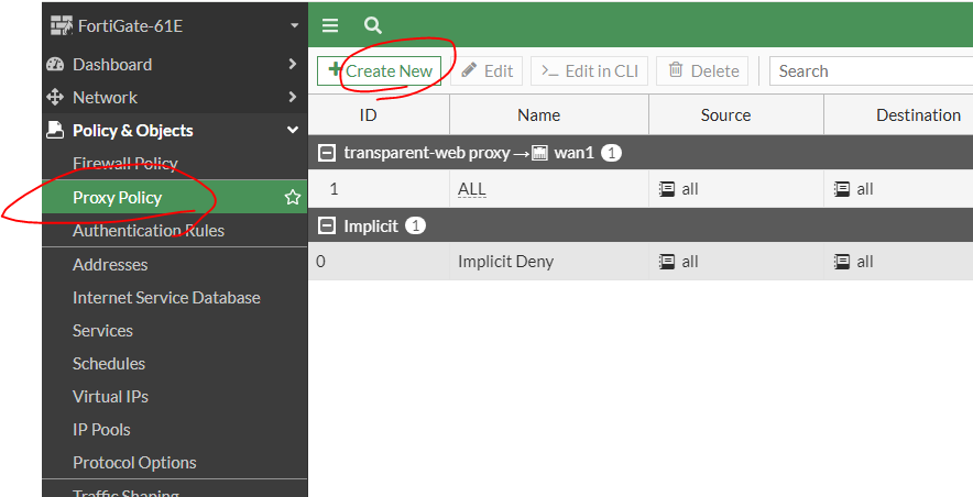
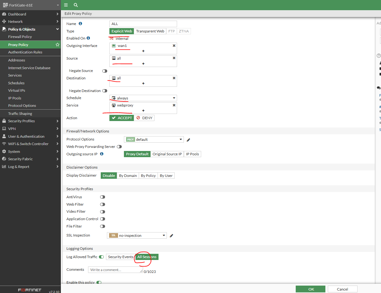
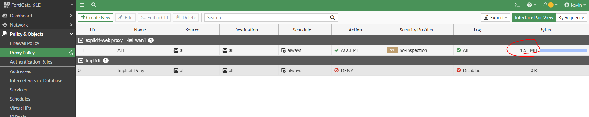
| [Fortigate-#18]- Explicit Proxy with UTM function (0) | 2024.12.23 |
| [Fortigate-#17]- Explicit Proxy (0) | 2024.12.23 |